
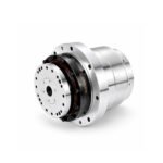
 Joint Rotary Actuators Series HAT
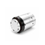 Joint Rotary Actuators series HAS
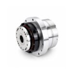 Joint Rotary Actuators Series HAMF
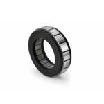 Frameless Torque Motor HBM
 Rotary Actuators
 Joint Rotary Actuators Series HAG
 Rotary Actuators Series HPG
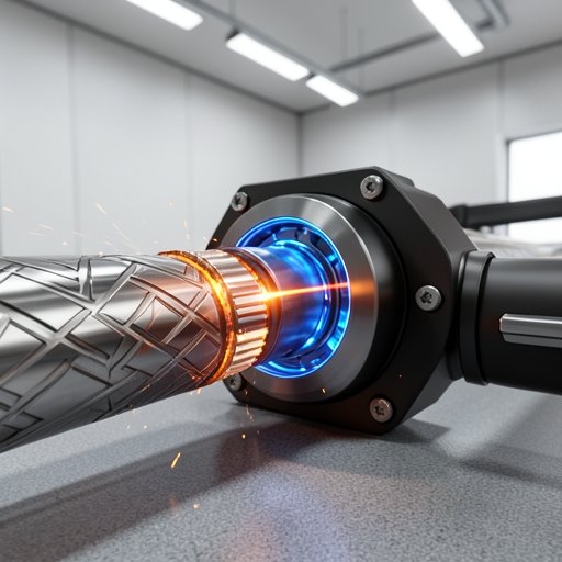
Introduction: The Invisible Hand Guiding the Laser Beam
The paradox of modern laser processing is that the cutting tool itself—the laser beam—is virtually perfect. It operates at the speed of light, possesses zero physical mass, and never dulls. Yet, achieving a flawless cut or weld relies entirely on the invisible hand guiding that beam: the mechanical motion control system.
When a laser cuts a complex contour, any hesitation, micro-vibration, or mechanical backlash in the machine translates directly into a defect on the workpiece. For machine builders, achieving flawless cuts requires overcoming the physical limits of high speed manufacturing. This article explores how advanced precision actuators and direct drive technologies are bridging the gap between optical perfection and mechanical reality in modern CNC laser equipment.
The Unique Dynamics of CNC Laser Equipment
Laser equipment demands a level of dynamic fidelity that far exceeds traditional milling or routing. Because there is no physical contact to dampen vibrations, the motion system must be inherently rigid and perfectly smooth.
Why Smooth Motion Matters for Cut Quality and Edge Finish
In laser cutting, the edge quality (often referred to as striation or surface roughness) is a direct reflection of the actuator’s performance. If a motor suffers from cogging torque or a gearbox introduces vibration, the laser beam will subtly tremble. At cutting speeds of several meters per minute, this micro-tremble manifests as visible, jagged lines along the cut edge, often necessitating costly secondary polishing operations.
Maintaining Constant Velocity During Complex Interpolation
When a CNC controller commands a laser head to cut a tight radius or a complex curve, multiple axes must move simultaneously (interpolation). The motion system must maintain an absolutely constant vector velocity. Any lag or “settling time” mismatch between the X, Y, and rotary axes will cause the laser to dwell too long in one spot, burning or over-melting the material.
Revolutionizing Tube Cutting with Hollow Rotary Actuators
One of the fastest-growing segments in the industry is CNC laser tube cutting, which relies heavily on high-performance rotary axes to manipulate the workpiece under the laser head.
The Critical Role of the Rotary Axis in Tube Machining
Unlike flat sheet cutting, tube machining requires the pipe to be rotated continuously and precisely in synchronization with the laser head’s linear movements. The rotary chuck must accelerate heavy metal tubes instantly while maintaining exact angular positioning to ensure cut geometries align perfectly.
Eliminating Backlash to Prevent Gouging on Direction Reversals
Traditional gearboxes have mechanical clearance between teeth, known as backlash. During a tube cutting operation, the rotary axis frequently reverses direction to track complex contours. If backlash is present, the tube will momentarily pause while the motor traverses the gap, causing the laser to gouge a hole in the material. Hobber Drive’s HAT series hollow rotary actuators solve this by utilizing strain wave gear technology, providing strict zero-backlash performance that ensures the tube never deviates from its commanded position.
Leveraging Hollow Bores for Automated Chuck Mechanisms
Modern laser tube cutters use automated pneumatic or electric chucks to grip the material. A large aperture actuator, such as the HAMF series, allows the pneumatic lines and sensor wires for the chuck to be routed directly through the center of the rotation axis. This clean, internal routing prevents cable tangling during infinite 360-degree rotation and drastically simplifies the machine’s overall design.
Direct Drive Motors for High-Speed Laser Marking and Drilling
For laser marking, etching, and micro-drilling, the process requires moving a lightweight laser mirror (galvanometer) or the workpiece itself over very short distances at extreme frequencies.
Overcoming Settling Time in Rapid Point-to-Point Operations
In point-to-point laser processing, the machine must move to a coordinate, stop, fire the laser, and move to the next coordinate in milliseconds. Mechanical transmissions introduce a “spring” effect that causes the load to vibrate after stopping. Direct drive technology eliminates this compliance. By coupling the load directly to the rotor, the system can stop and settle almost instantaneously, maximizing the number of marks or holes processed per second.
Enhancing Dynamic Response with Frameless Technology
To achieve this blistering speed, engineers turn to frameless torque motors, like the HBM series. By integrating the motor’s stator and rotor directly into the laser head or indexing stage, designers eliminate the weight and inertia of external couplings and motor housings. This ultra-low inertia design allows for the explosive acceleration required in high speed optical applications.
High Rigidity Requirements in 3D Laser Welding
3D laser welding, often performed by multi-axis robotic arms, introduces another layer of complexity: combining high power with spatial flexibility.
Preventing Micro-Vibrations During High-Power Welding Cycles
Laser welding requires the focal point to remain perfectly steady to ensure proper weld penetration and pool dynamics. If the robotic joints lack torsional stiffness, the extended arm will act like a tuning fork, amplifying tiny motor vibrations into massive errors at the weld seam.
Integrating Robotic Joint Modules for 5-Axis Laser Heads
To combat this, 5-axis laser welding heads and robotic arms rely on highly integrated robotic joint modules. These modules combine high-torque motors with exceptionally rigid precision gearboxes and heavy-duty cross-roller bearings. This high-rigidity architecture resists overturning moments and effectively dampens vibrations, ensuring the laser focal point remains locked on target, regardless of the arm’s spatial orientation.
Conclusion: Hardware That Matches the Speed of Light
The ultimate quality and throughput of a laser machine are strictly dictated by its motion hardware. You cannot fix mechanical backlash, poor rigidity, or high-frequency jitter with software patches.
To fully harness the speed and precision of modern laser sources, equipment manufacturers must build their machines on a foundation of zero-backlash actuators and highly responsive direct drive motors. By selecting components engineered for flawless dynamic performance, machine builders can ensure their CNC laser systems operate as flawlessly as the beams they guide.
FAQ Section: Motion Control for Laser Systems
Q1: How does mechanical backlash affect a laser cut profile?
Mechanical backlash causes a momentary loss of motion control when an axis reverses direction. Because the laser remains active during this mechanical pause, it melts or burns a larger area of the material, resulting in a visible “gouge,” burn mark, or an out-of-tolerance dimension on the final part.
Q2: Why are direct drive systems preferred over gearboxes for rapid laser marking?
Laser marking involves extremely short, high-frequency movements. Gearboxes introduce friction, elasticity, and inertia, which increase the “settling time” (the time required for vibrations to stop). Direct drive systems eliminate these mechanical delays, allowing the laser to fire faster and more accurately.
Q3: Do your rotary actuators offer the IP rating needed to resist laser cutting dust?
Yes. Laser cutting generates fine, abrasive metallic dust. Precision rotary actuators used in these environments must be fully sealed. High-quality industrial actuators offer IP65 or IP67 ratings, ensuring that internal bearings and gears are completely protected from particulate contamination, ensuring a long operational lifespan.