
Designing a high-performance robotic arm presents many engineering challenges. Perhaps the most critical decision is choosing the right actuator for each joint. that guarantees performance without compromising the design? This guide provides a clear, step-by-step process to help you select the right rotary actuator for your project. For expert guidance, you can always .
Step 1: Define Your Application and Key Performance Requirements
Before diving into datasheets, you must first define what your robotic arm needs to accomplish. What are your primary performance goals? Answering this question clarifies your selection criteria from the start.
Understanding Your Payload Capacity and Reach
First, determine the maximum weight (payload capacity) your robotic arm will carry. Also, consider the total length or reach of the arm. A heavier payload at a longer distance will significantly increase the torque required at the base joints. This initial analysis is fundamental to proper sizing.
Determining Required Speed and Acceleration
Next, define the operational speed for your application. How fast does the robotic arm joint need to move, and how quickly must it accelerate? High-speed applications, like pick-and-place robots, demand actuators with excellent dynamic response and thermal management.
What Level of Positional Accuracy and Repeatability is Needed?
Finally, consider your precision requirements. Applications like welding or inspection require high positional accuracy and repeatability. This will directly influence your choice of gearbox technology and encoder resolution. For less demanding tasks, you might have more flexibility.
Step 2: Calculating Torque for Your Robotic Arm Joint
With your performance goals defined, the next step is to calculate torque. What torque do I need for a robotic arm? This is a question every engineer must answer accurately to avoid underperformance or oversizing.
Static Torque vs. Dynamic Torque: What’s the Difference?
Static torque is the holding torque required to keep a load stationary against gravity. Dynamic torque is the torque needed to accelerate the arm and its payload. You must calculate both to ensure your actuator can handle all operational phases.
A Simplified Formula for Estimating Dynamic Torque
A basic formula for dynamic torque is T = I * α (Torque = Moment of Inertia * Angular Acceleration). Calculating the precise moment of inertia (I) for a complex arm can be difficult. However, you can start with simplified models to get a reliable estimate. Always account for both the arm’s inertia and the payload’s inertia.
Don’t Forget the Safety Factor
How to calculate the safety factor? After calculating your required torque, always apply a safety factor. This accounts for unforeseen friction, voltage drops, and other variables. A typical safety factor ranges from 1.5 to 2.0, ensuring your system has enough headroom.
Step 3: Evaluating Mechanical Specifications of a Hollow Rotary Actuator
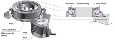
Once you have your torque requirements, you can start comparing specific hollow rotary actuator models. How does a hollow actuator work? It integrates a motor and gearbox into a single unit with a central hole, simplifying design.
The Importance of Torsional Rigidity and Stiffness
Torsional rigidity is a measure of how much an actuator deflects under torque. High rigidity is crucial for maintaining accuracy under load, especially in applications with sudden stops or direction changes. It directly impacts the system’s responsiveness and stability.
Why Zero Backlash Matters for Precision Tasks
Zero backlash is essential for high-precision applications. Backlash, or the play between gear teeth, can cause significant positioning errors. Actuators using strain wave gears, like many in our catalog, offer near-zero backlash performance, making them ideal for robotics. You can on our website.
Sizing the Hollow Bore for Your Cable and Tubing Needs
The primary advantage of a hollow actuator is its central opening. Ensure the hollow bore diameter is large enough to pass all necessary cables, air lines, or even other mechanical parts. This feature dramatically simplifies cable management and creates a cleaner, more reliable design.
Step 4: Considering the Electrical and System Integration Aspects
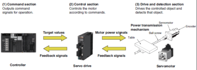
Finally, consider how the actuator will integrate into your larger control system. A perfect mechanical fit is useless without proper electrical and software compatibility. This is a key part of modern robotics engineering.
Matching the Actuator with the Right Servo Driver
The actuator and servo driver must be a matched pair. The driver needs to supply the correct voltage and current to meet the motor’s performance requirements. Using a pre-matched system from a single supplier like Hobber Drive simplifies this process and guarantees compatibility.
Encoder Resolution: How Much Feedback is Enough?
The encoder provides position feedback to the controller. Higher encoder resolution allows for more precise positioning and smoother velocity control. The required resolution depends entirely on your application’s accuracy demands.
Communication Protocols and System Compatibility
Ensure the actuator’s servo driver supports a communication protocol compatible with your main controller (e.g., a PLC). Common protocols include EtherCAT, CANopen, and Modbus. Proper system integration is key to a successful project.
Conclusion: Making the Right Choice for Your Robotic Arm Joint
Selecting the right hollow rotary actuator involves a systematic process of defining requirements, calculating loads, and evaluating specifications. By following these four steps, you can confidently choose a component that ensures the performance and reliability of your robotic arm joint. While this guide provides a solid framework, consulting with an expert can prevent costly errors. for a free consultation on your project.
FAQ Section: Common Questions About Selecting a Rotary Actuator
Q1: What is the difference between hollow and solid shaft? A hollow shaft actuator has a central bore, which is ideal for passing cables and creating a compact design. A solid shaft actuator often provides slightly higher torsional rigidity and can be a simpler solution when passthrough is not needed.
Q2: How much of a safety factor should I use in my torque calculations? We recommend a safety factor of at least 1.5. For applications with high dynamic loads or significant unknown variables, a factor of 2.0 or even higher may be appropriate to ensure long-term reliability.
Q3: Can I use a hollow rotary actuator for a vertical (gravity-loaded) axis? Yes, absolutely. However, for vertical applications, you must ensure the actuator has a brake. The brake will hold the arm’s position against gravity when the motor is powered off, which is a critical safety feature.
Q4: Is a higher gear ratio better? Not always. A higher gear ratio increases output torque and resolution but decreases output speed. The ideal ratio is a trade-off that depends on your specific speed and torque requirements. To find the best fit, you can .