 Joint Rotary Actuators Series HAT
 Joint Rotary Actuators series HAS
 Joint Rotary Actuators Series HAMF
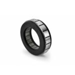 Frameless Torque Motor HBM
 Rotary Actuators
 Joint Rotary Actuators Series HAG
 Rotary Actuators Series HPG

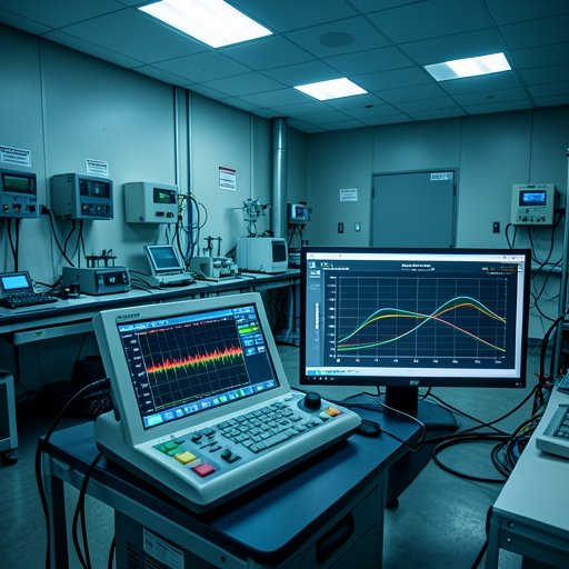
In high-precision industries such as semiconductor wafer inspection, advanced optical scanning, aerospace gimbals, and high-end metrology, motion systems require an exceptional degree of smoothness. Engineers designing these applications push the boundaries of mechanical and electrical performance, striving for sub-micron positioning and velocity uniformity.
However, even the most sophisticated motion platforms can be compromised by a subtle yet persistent phenomenon: torque ripple. When left unaddressed, torque ripple introduces velocity variations, micro-vibrations, and tracking errors that degrade overall system performance. Understanding the root causes of torque ripple and how to minimize it through proper component selection and control optimization is vital for achieving ultra-smooth motion.
What is Torque Ripple and Where Does It Come From?
Torque ripple refers to the periodic fluctuation in the output torque of a motor as it rotates through different electrical and mechanical angles. Under ideal conditions, a motor should deliver a perfectly constant torque for a steady current input. In reality, several electromagnetic and mechanical factors conspire to create variations:
- Cogging Torque: This is the magnetic interaction between the permanent magnets on the rotor and the slotted iron core of the stator. Even with zero current applied, cogging torque causes the motor to “notch” or resist smooth rotation, which is particularly disruptive at low speeds.
- Back-EMF and Magnetic Harmonics: Non-sinusoidal magnetic field distributions within the air gap generate higher-order harmonics, leading to fluctuations in output torque as the rotor moves relative to the stator winding.
- Current and Commutation Ripple: Imperfections in the drive’s current loop, PWM (Pulse Width Modulation) switching noise, and non-ideal commutation profiles can inject current harmonics that directly translate into dynamic torque variations.
The Impact of Torque Ripple on Precision Systems
The presence of torque ripple manifests in several detrimental ways, directly undermining the goals of high-precision engineering:
- Velocity Ripple and Low-Speed “Crawling”: At very low rotational speeds, torque ripple can cause the motor to stutter or crawl rather than rotate smoothly. This ruins applications like constant-velocity optical scanning or continuous inspection.
- Tracking and Positioning Errors: In closed-loop servo systems, torque ripple forces the controller to constantly overcorrect, leading to phase lag, increased settling time, and reduced contouring accuracy.
- Acoustic Noise and Wear: High-frequency torque variations induce mechanical resonance in structural components, generating audible noise and accelerating mechanical fatigue over time.
Effective Strategies to Minimize Torque Ripple
Mitigating torque ripple requires a two-pronged approach: optimizing the physical hardware architecture and implementing advanced software compensation.
1. Hardware Optimization: Choosing the Right Motor Technology
- Use Frameless Torque Motors: Direct-drive frameless torque motors—characterized by their large-diameter, short-stack, and high-pole-count design—inherently distribute and minimize harmonic distortion better than traditional fractional-pole framed motors.
- Advanced Electromagnetic Design: Selecting motors engineered with fractional-slot concentrated windings, optimized magnet skewing, or specialized pole-slot combinations can drastically reduce cogging torque at the manufacturing level.
2. Control and Drive-Level Compensation
- Advanced Current Reconstruction: Modern servo drives utilize high-resolution feedback devices and sophisticated sinusoidal commutation algorithms to ensure clean, low-distortion current delivery.
- Feedforward Torque Compensation: High-performance servo controllers can map a motor’s specific torque ripple profile across a full mechanical revolution. By injecting a real-time, phase-inverted compensation current, the drive actively cancels out the inherent ripple before it manifests as physical motion error.
Conclusion
Torque ripple is an inevitable physical reality in electric motors, but it does not have to be a performance bottleneck. By combining inherently smooth, low-cogging hardware—such as precision frameless torque motors—with advanced drive-level tuning and feedforward compensation, engineers can successfully eliminate jitter and achieve the ultra-smooth motion required by today’s most demanding applications.
Frequently Asked Questions (FAQ)
Q1: What is the main difference between cogging torque and torque ripple?
A1: Cogging torque is a specific component of torque ripple that occurs passively due to the magnetic attraction between the rotor magnets and the stator iron slots without any electrical current applied. Torque ripple is the broader umbrella term that includes cogging torque as well as active electromagnetic and commutation-related fluctuations when the motor is powered.
Q2: How do frameless torque motors help reduce torque ripple?
A2: Frameless torque motors feature a high pole-count and large-diameter direct-drive design. This geometry naturally smooths out electromagnetic variations and eliminates intermediate mechanical transmissions (like belts or gearboxes), which helps deliver exceptionally low torque ripple and high stiffness.
Q3: Can software compensation completely eliminate torque ripple?
A3: While software-based feedforward compensation and advanced drive tuning can dramatically reduce torque ripple (often by 80% or more), combining it with a high-quality, inherently low-cogging motor design yields the best results for ultra-precision systems.