 Joint Rotary Actuators Series HAT
 Joint Rotary Actuators series HAS
 Joint Rotary Actuators Series HAMF
 Frameless Torque Motor HBM
 Rotary Actuators
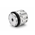 Joint Rotary Actuators Series HAG
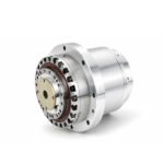 Rotary Actuators Series HPG
Introduction: The “Bumpiness” in Precision Motion
Have you ever turned a permanent magnet motor by hand while the power was off and felt a series of “detents” or a jerky, rhythmic resistance? In the world of motion control, this is known as cogging torque. While it might seem harmless in a standard power tool, in a high-precision robotic joint or a medical scanner, this “bumpiness” is a major barrier to performance.
Cogging torque is the silent enemy of smooth motion. It introduces unwanted vibrations, limits the stability of your velocity loop, and can even cause positioning errors. If your application requires fluid movement at low speeds, achieving a low cogging profile is not optional—it is a requirement. This guide will explain why cogging happens and how to eliminate it from your system.
What is Cogging Torque? The Physics of Magnetism
Cogging torque is an iron-core phenomenon. It is purely the result of the magnetic attraction between the permanent magnets on the rotor and the steel teeth of the stator.
The Interaction Between Rotor Magnets and Stator Teeth
Magnetic flux always seeks the path of least resistance (reluctance). As the rotor turns, the magnets naturally want to align with the stator teeth to close the magnetic circuit. This creates a “preferred” position. To move the rotor away from this alignment, the motor must overcome this magnetic pull, resulting in a torque that varies with the rotor’s position.
Why Cogging Exists Even When the Motor is Powered Off
Because cogging torque is caused by the physical geometry and magnetic properties of the motor components, it exists independently of any electrical current. It is a “passive” force. This distinguishes it from other types of torque fluctuations that only occur when the motor is running.
How Cogging Torque Affects Your System Performance
In high-end industrial automation, the presence of significant cogging torque can cripple an otherwise well-designed machine.
Speed Ripples: The Barrier to Ultra-Smooth Low-Speed Rotation
When a motor rotates at high speeds, inertia often masks the effects of cogging. However, at low speeds (below 10 RPM), cogging torque causes noticeable “speed ripples.” The motor speeds up and slows down as it passes each stator tooth, making it impossible to achieve the constant velocity required for high-quality scanning or inspection.
Positioning Errors and Settling Time Challenges
Cogging torque acts as a non-linear disturbance. When a servo attempts to settle into a precise position, the cogging force can “pull” the rotor slightly away from the target or cause the controller to oscillate as it fights the magnetic detent. This increases settling time and decreases repeatability.
Audible Noise and Mechanical Vibration
The repetitive nature of cogging forces creates mechanical vibrations that can resonate through the machine frame. This not only causes audible noise—often a high-pitched whine or hum—但 also leads to premature wear on bearings and couplings.
Cogging Torque vs. Torque Ripple: Clearing the Confusion
In technical discussions, these two terms are often used interchangeably, but they are technically different.
Identifying Electromagnetic Torque Ripple
While cogging is a passive mechanical-magnetic effect, torque ripple is typically an active effect. Torque ripple includes cogging but also encompasses fluctuations caused by the interaction between the motor’s current and its back-EMF (electromagnetic factors).
Why the Distinction Matters for Servo Tuning
Identifying the source of the vibration is key to solving it. Active torque ripple can often be mitigated through advanced drive algorithms (like field-oriented control), whereas cogging torque is a physical property that is best solved through superior motor design.
Engineering Solutions: How Hobber Achieves Low Cogging
At Hobber Drive, we believe that the best way to handle cogging is to minimize it at the source through meticulous engineering.
Advanced Slot-Pole Combinations and Skewing Techniques
The ratio of stator slots to rotor poles is a critical design factor. By selecting specific “fractional slot” combinations, we can ensure that the magnets never align perfectly with all teeth at once, effectively canceling out the cogging forces. Additionally, we utilize “skewing”—aligning magnets or stator laminations at a slight angle—to smooth out the transition from one tooth to the next.
The Impact of High-Grade Magnetic Materials
The quality and shape of the magnets play a vital role. Using high-grade Neodymium magnets with optimized edge profiles allows for a more gradual change in magnetic flux, contributing to a much lower torque deviation.
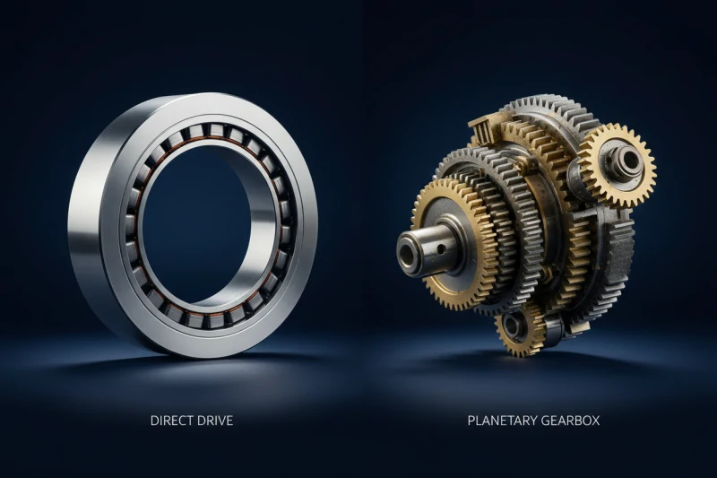
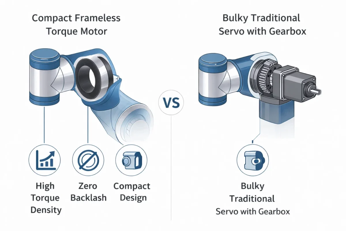
Why Frameless Motors Offer Superior Potential for Optimization
A frameless motor allows the designer to have more control over the final integration. Because the stator and rotor are integrated directly into the machine’s bearings, the air gap can be maintained with extreme precision. A consistent, optimized air gap is the final key to ensuring the low cogging performance promised on the datasheet is realized in the actual application.
Conclusion: Eliminate Jitter at the Source
While modern digital servo drives offer software compensation to “fight” cogging, these are often just band-aids. Software compensation increases the complexity of the control loop and can introduce its own latency issues.
The most robust solution is to choose a motor that is inherently smooth. For high-precision applications—from surgical robots to semiconductor inspection—selecting a motor with a proven low cogging profile ensures that your system starts with the highest possible performance ceiling. Eliminate the jitter at the mechanical source, and your control system will be free to focus on what matters: absolute precision.
FAQ Section: Managing Motor Cogging
Q1: Can I use software to compensate for cogging torque?
Yes, many high-end drives allow you to map the cogging torque of a motor and apply an equal and opposite current command to cancel it out. However, this requires a very high-resolution encoder and adds complexity to the setup process.
Q2: Does a higher pole count always mean less cogging?
Not necessarily. While a higher pole count increases the frequency of the cogging, it doesn’t always decrease the magnitude. The relationship between the number of slots and poles is far more important than the absolute number of either.
Q3: How do I measure the cogging torque of my frameless motor?
The most accurate way is to use a torque transducer while back-driving the unpowered motor at a constant, slow speed. The peak-to-peak variation in the torque reading is the cogging torque. Most manufacturers provide this value as a percentage of the rated torque.