 Joint Rotary Actuators Series HAT
 Joint Rotary Actuators series HAS
 Joint Rotary Actuators Series HAMF
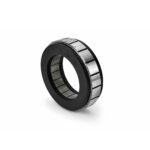 Frameless Torque Motor HBM
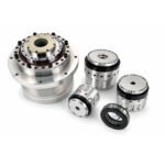 Rotary Actuators
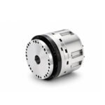 Joint Rotary Actuators Series HAG
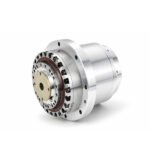 Rotary Actuators Series HPG
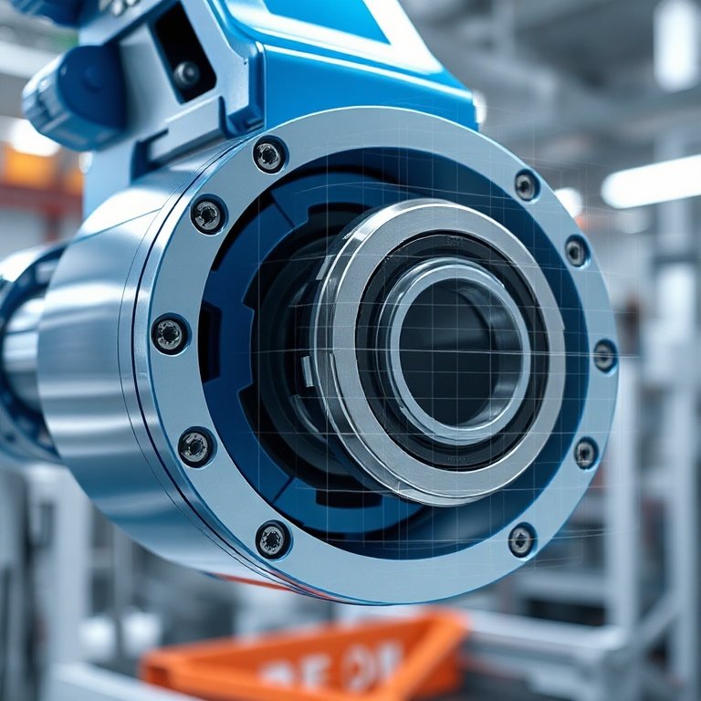
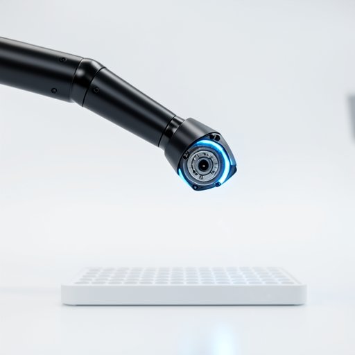
Introduction: The Backbone of Precision
In the design of modern automation, engineers frequently prioritize motor torque, speed, and encoder resolution. While these are essential, they are often undermined by a neglected factor: torsional stiffness. You can have the most powerful motor and the most advanced controller, but if the mechanical joint itself is “soft,” your system will never achieve high-level performance.
The mechanical integrity of the joint is the backbone of precision. If a robotic joint cannot resist twisting under load, the end-effector will drift, oscillate, and fail to reach its target coordinates reliably. This article explores why torsional stiffness is the silent determinant of robot accuracy.
What is Torsional Stiffness?
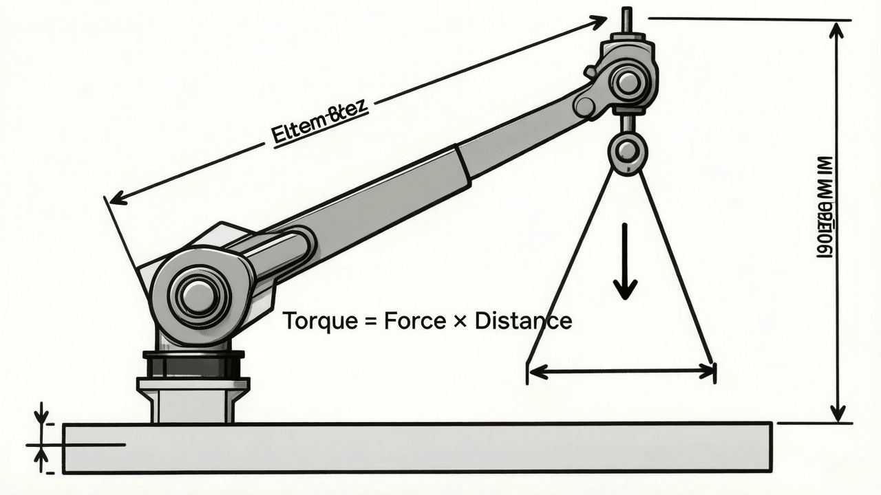
At its core, torsional stiffness defines how much a joint resists twisting when a load or cutting force is applied to it.
Defining the Elasticity of a Robotic Actuator
Every material has a degree of elasticity. When you apply torque to an actuator, the housing, bearings, and gear teeth will deflect—even if only by a fraction of a degree. This deflection is the inverse of stiffness. A high-stiffness joint resists this deformation, keeping the output perfectly synchronized with the motor input.
The Relationship Between Torque, Deflection, and Stiffness
The relationship is expressed as K = T / θ, where K is stiffness, T is torque, and θ is the angular deflection. To maximize precision, your goal is to minimize θ (deflection) for any given T (torque). In the world of high-end robotics, we measure this in Newton-meters per arc-minute (Nm/arc-min).
Impact on Robot Accuracy and Repeatability
A joint with low stiffness acts like a rubber band rather than a rigid link. This causes measurable issues in real-world operation.
Minimizing Deflection Under Dynamic Loads
Robots rarely move in a vacuum. They carry payloads that create varying forces. If a robot arm is stiff, it ignores these varying forces and stays on its programmed path. If it lacks stiffness, the arm will “sag” or twist under the load of the payload, leading to positioning errors that change depending on where the robot is in its workspace.
Improving Path-Following Accuracy in High-Speed Motion
When a robot makes a rapid direction change, the inertia of the arm creates a “wind-up” effect in the joints. High torsional stiffness ensures that the mechanical structure responds instantly. Low-stiffness joints, by contrast, experience a delay between the motor’s movement and the joint’s actual output, causing the arm to overshoot or deviate during high-speed contouring.
Control Loop Stability and Bandwidth
Mechanical stiffness isn’t just a physical requirement; it is a critical constraint for your control algorithms.
High Rigidity and Higher Control Bandwidth
A servo system’s “bandwidth” refers to how quickly it can react to errors. A stiff mechanical system allows you to tune the servo gains much higher without inducing oscillations. If your joint is “floppy,” you are forced to turn down your control gains to prevent the system from shaking itself apart, effectively crippling your robot’s speed and accuracy.
Suppressing Resonance to Avoid Servo Oscillations
Every mechanical system has a natural resonant frequency. A low-stiffness joint has a low natural frequency, which is often within the range of the servo motor’s operational commands. This leads to resonance, vibration, and loud grinding noises. High rigidity pushes this resonant frequency higher, safely outside the range of normal operation.
Engineering High Rigidity into Robotic Actuators
Building a stiff joint is an exercise in material science and geometric optimization.
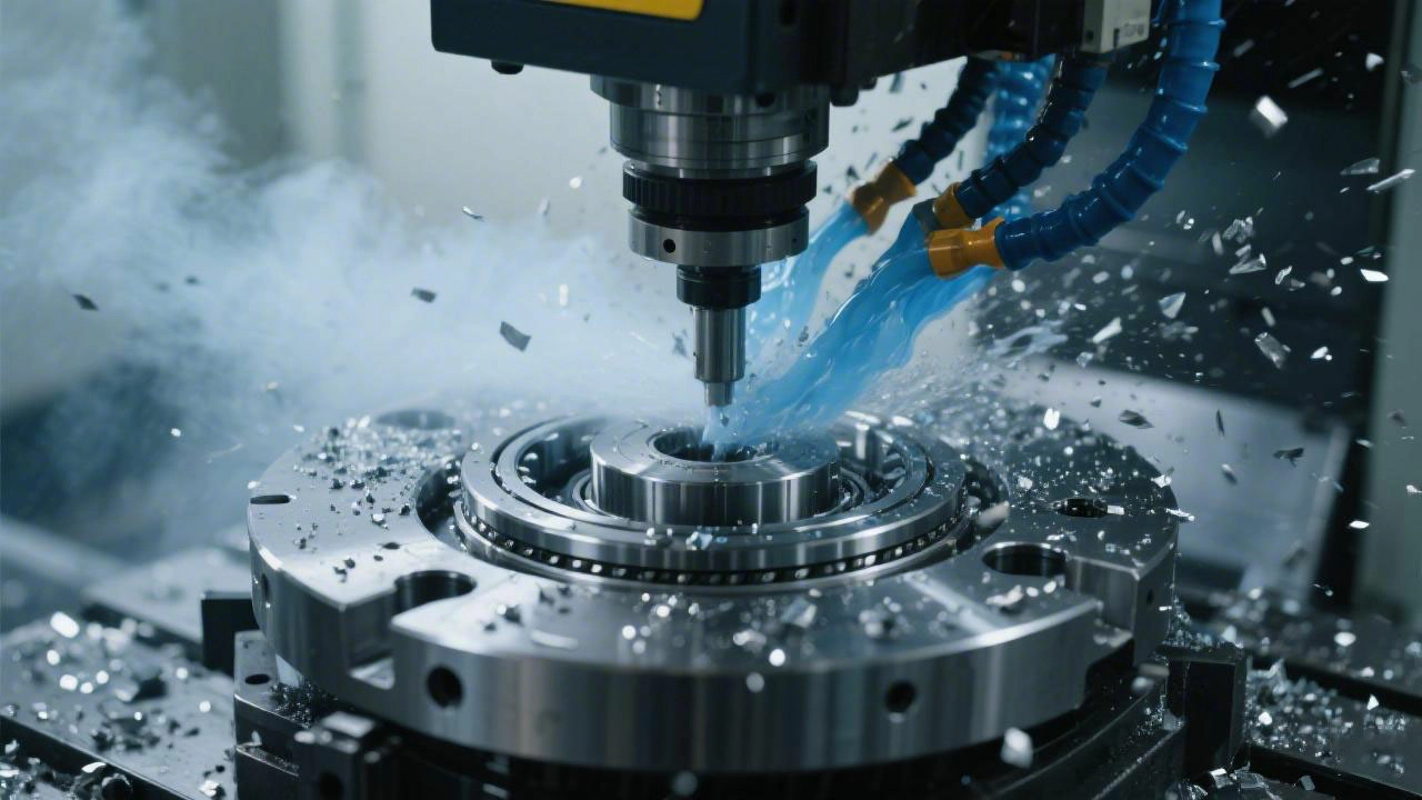
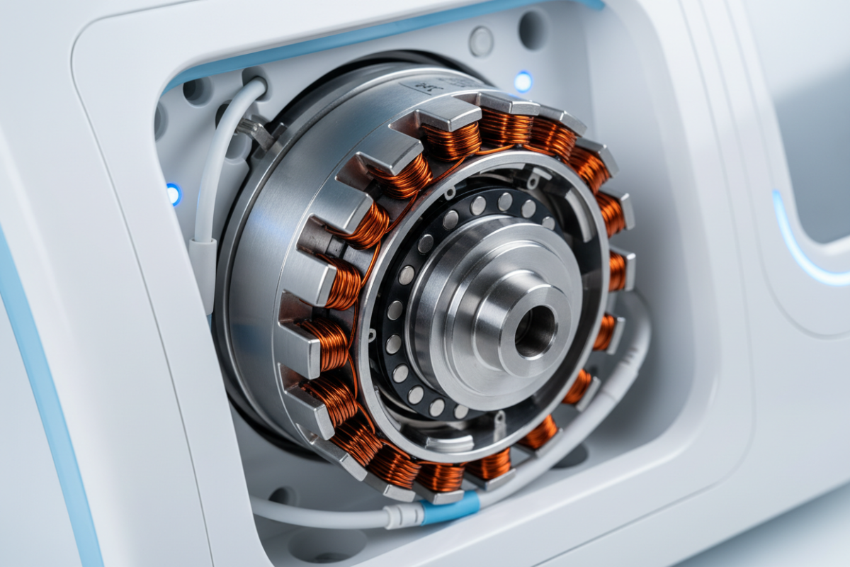
Advanced Bearing Configurations for High Overturning Stiffness
The bearings are the primary interface for loads. We utilize large-diameter cross-roller bearings that can handle high axial, radial, and moment loads simultaneously. This configuration ensures that the joint does not tilt or wobble under complex loading.
Optimizing Housing Materials and Wall Thickness
Mass is not always rigidity. We use high-grade aluminum or steel alloys with finite element analysis (FEA) optimized wall thicknesses. By strategically adding material only where it resists deformation, we achieve a balance of high stiffness and low overall joint mass.
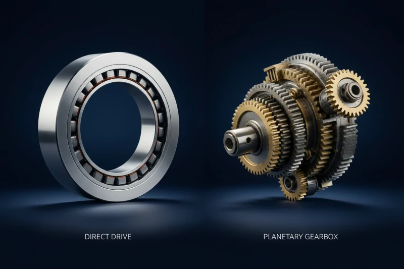
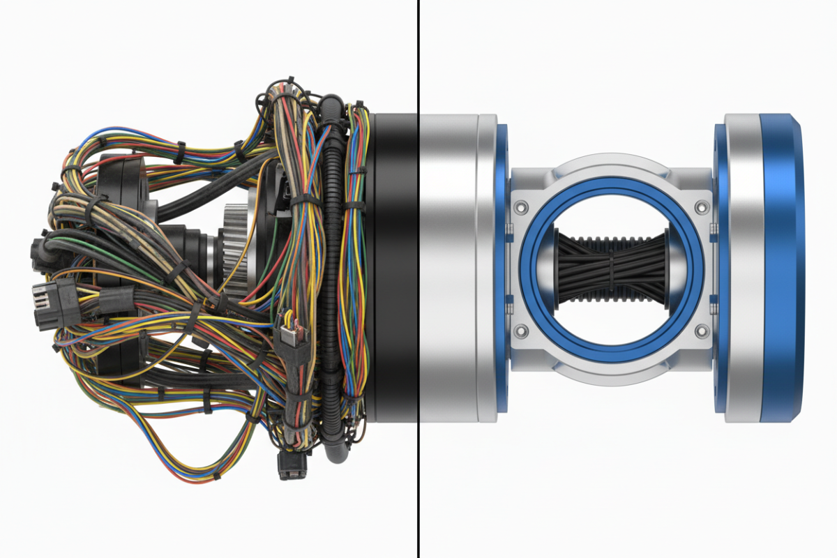
The Role of Precision Gearing in System Stiffness
The internal gearbox is the final link. Strain wave gears (harmonic reducers) provide a unique advantage here; because they engage many teeth at once, they distribute the load over a larger area, resulting in much higher stiffness compared to standard planetary systems where only a few gear teeth bear the load.
Conclusion: Designing for Peak Performance
The link between hardware rigidity and final machine performance is absolute. When you select a robotic joint, you are not just buying a motor and a gearbox; you are buying the structural foundation of your robot’s precision.
By refusing to compromise on stiffness, you ensure your system remains stable, accurate, and responsive throughout its entire service life. Always treat torsional stiffness as a primary design parameter, not a secondary spec.
FAQ Section: Robotic Joint Rigidity FAQs
Q1: How does torsional stiffness affect my PID tuning? Higher stiffness allows for higher gain settings in your PID loop. A stiffer joint responds faster to errors without becoming unstable, whereas a flexible joint forces you to use lower, more conservative gains to avoid vibration.
Q2: Can an actuator be too rigid? In terms of pure motion control, rigidity is rarely “too high.” However, extreme rigidity in a lightweight frame can sometimes lead to stress fractures if the structure is not designed to handle the forces. It is about balancing the actuator’s stiffness with the overall frame design.
Q3: How do you test the torsional stiffness of an integrated module? We lock the input shaft and apply a known torque to the output flange while measuring the angular displacement with a high-precision laser interferometer. This allows us to generate a precise stiffness curve for every model in our catalog.