 Joint Rotary Actuators Series HAT
 Joint Rotary Actuators series HAS
 Joint Rotary Actuators Series HAMF
 Frameless Torque Motor HBM
 Rotary Actuators
 Joint Rotary Actuators Series HAG
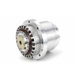 Rotary Actuators Series HPG
Introduction: Bridging the Gap Between Power and Motion
In the field of electrical engineering, the servo drive is the essential gatekeeper of performance. A properly executed servo drive sizing process ensures that your motor receives exactly the power it needs to perform its task without compromise.
If you under-size a drive, you face constant nuisance trips, overheating, and a system that fails to meet its production targets. If you over-size, you waste budget and valuable cabinet space. Creating a reliable servo system starts with accurate math. This guide walks you through the essential steps to size your drive correctly every time.
Step 1: Gathering Your Motor and Application Data
Before you can choose a drive, you must understand the “muscle” it will be controlling. Your motor’s datasheet and your application’s motion profile are your primary source of truth.
Rated vs. Peak Torque and Speed Requirements
You must define the maximum speed your application requires and the torque needed at that speed. Distinguish between the continuous torque (what the motor can do all day) and the peak torque (what is needed for rapid acceleration). These values dictate the current limits of your drive.
Motor Constants: Ke (Back-EMF) and Kt (Torque Constant)
Every motor has electrical signatures. The Ke constant tells you how much voltage the motor generates back to the drive as it spins, while the Kt constant defines the relationship between current and torque. These are vital for calculating your power requirements.
Step 2: Calculating Voltage Requirements
The voltage of your servo system determines the “speed ceiling” of your motor.
The Impact of Bus Voltage on Top Speed
As a motor spins faster, it generates Back-EMF. If this voltage approaches the drive’s supply voltage, the motor cannot spin any faster. When sizing, ensure your drive’s DC bus voltage is high enough to overcome the Back-EMF at your maximum required RPM, plus a 10-20% margin for control overhead.
Why Low Voltage Servo Drives are Rising in Popularity
In many mobile robotics and battery-powered applications, low voltage servo drives (e.g., 24V or 48V DC) are becoming the standard. They offer high safety and compact integration. However, they require careful sizing because lower voltage means you need higher current to achieve the same power output.
Step 3: Determining Continuous (RMS) and Peak Current
Current is directly proportional to torque. This is the most critical part of the sizing process.
How to Calculate RMS Current Based on Your Motion Cycle
Motors don’t usually run at full power 100% of the time. You need to calculate the Root Mean Square (RMS) torque of your cycle—accounting for acceleration, constant speed, deceleration, and dwell time. The drive’s continuous current rating must exceed this RMS value to prevent the motor and drive from overheating.
Planning for Peak Demand During Acceleration
Peak current is what gets the load moving. Most high-performance drives can provide a “peak” output (often 200% to 300% of continuous) for a short duration (typically 1 to 3 seconds). Ensure your drive’s peak current rating covers the highest point on your motion profile’s torque curve.
Step 4: Communication Protocol and Controller Compatibility
A drive is only as useful as its ability to listen to the motion controller.
Integrating with EtherCAT, CANopen, or Pulse Trains
The control interface is just as important as the power rating. If your system uses a high-speed PLC, an EtherCAT-capable drive is usually required for real-time synchronization. Ensure the drive’s control hardware can handle the update rates required by your motion controller.
Ensuring Feedback Resolution Matches the Drive Capabilities
Your encoder resolution must be compatible with the drive’s input electronics. If you are using a high-resolution absolute encoder for precision robotics, verify that the drive can process that specific serial protocol (e.g., BISS-C or Tamagawa) at high frequencies.
Conclusion: A Reliable System Starts with Accurate Sizing
Successful servo drive sizing is a disciplined balance of electrical capacity and mechanical demand. By following these four steps—gathering data, verifying voltage, calculating current, and ensuring controller compatibility—you build a foundation for a machine that is both efficient and durable.
A high-performance servo system should be invisible to the operator, running reliably in the background. Taking the time to perform these calculations during the design phase is an investment that pays off in reduced downtime and superior machine performance.
FAQ Section: Servo Drive Sizing Challenges
Q1: Can I use a drive with a higher power rating than the motor?
Yes. In fact, having a drive with a higher current capacity than the motor is safe and can provide a better safety margin. The drive’s software will allow you to limit the current to protect the smaller motor.
Q2: How does ambient temperature affect my drive’s current capacity?
Heat is the enemy of electronics. Most drives are rated for 40°C or 50°C. If your control cabinet is hotter than this, you must “de-rate” the drive, meaning its effective current capacity decreases. Always plan for the worst-case thermal environment.
Q3: What is the rule of thumb for the safety margin in current?
For industrial automation, we recommend a safety margin of at least 20%. If your calculated RMS current is 10 Amps, select a drive capable of at least 12 Amps continuous. This headroom accounts for mechanical wear, friction increases over time, and unexpected load fluctuations.