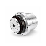
 Joint Rotary Actuators Series HAT
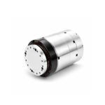 Joint Rotary Actuators series HAS
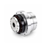 Joint Rotary Actuators Series HAMF
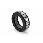 Frameless Torque Motor HBM
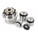 Rotary Actuators
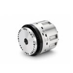 Joint Rotary Actuators Series HAG
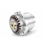 Rotary Actuators Series HPG
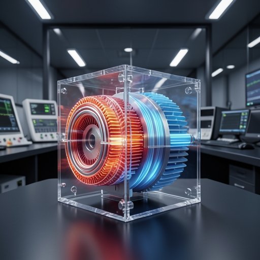
Introduction: The Hidden Heat in High-Performance Motion
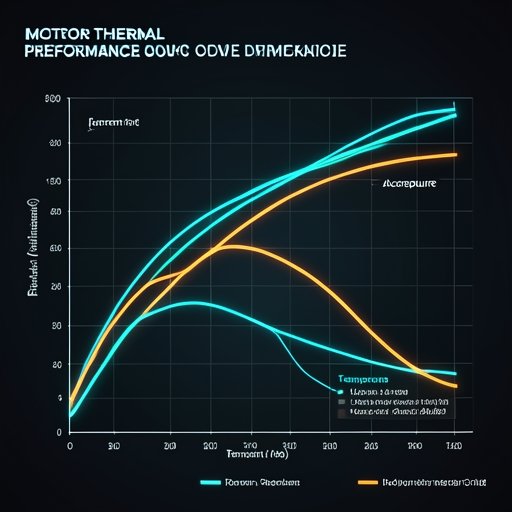
In the world of precision motion control, heat is more than just a byproduct; it is a fundamental constraint on motor performance. When pushing the limits of torque and speed, the electrical energy that doesn’t turn into mechanical work inevitably turns into heat. For high-torque applications like robotic joints or CNC spindles, this heat can lead to a cascade of failures, from reduced accuracy to permanent hardware damage.
Effective thermal management is not an afterthought—it is a cornerstone of system reliability. A motor that runs too hot will experience magnet degradation, insulation breakdown, and thermal expansion that destroys tight tolerances. This guide explores the best practices for identifying, managing, and mitigating heat in your high-performance motion systems.
Why Thermal Management is Critical for High Torque Motors
High-torque motors, especially frameless designs, generate significant energy density. Without a clear path for that energy to escape, the system’s performance ceiling drops rapidly.
The Impact of Heat on Permanent Magnets and Insulation
Most high-performance motors use Neodymium magnets. These magnets have a “Curie temperature” at which they lose their magnetic properties. Even before reaching that point, high heat reduces the motor’s torque constant (Kt), meaning you need more current to produce the same torque, which in turn creates even more heat. Furthermore, excessive temperatures accelerate the aging of wire insulation, leading to short circuits and total system failure.
How Thermal Expansion Destroys Sub-Micron Precision
In precision machining and semiconductor handling, accuracy is measured in microns. As a high torque motor heats up, the metal components in the actuator housing and the machine frame expand. This “thermal growth” causes positioning drift that software often cannot compensate for, resulting in rejected parts and lost productivity.
Identifying the Sources of Heat in Your Motion System
To manage heat, you must first understand where it comes from. There are three primary contributors in a precision motion axis.
Copper Losses (I²R) and Iron Losses (Eddy Currents)
“Copper loss” is heat generated by current flowing through the resistance of the motor windings. It increases with the square of the current, making it the dominant heat source during high-torque maneuvers. “Iron loss” occurs in the stator’s steel laminations due to rapidly changing magnetic fields (eddy currents and hysteresis), which becomes more significant at high operational speeds.
Friction from Seals and Bearings in Integrated Joints
In an integrated robotic joint module, mechanical friction is a secondary but important heat source. High-contact seals used for IP-rated protection and preloaded cross-roller bearings generate heat through constant friction. If not properly lubricated and dissipated, this heat can migrate into the motor and encoder.
Best Practices for Effective Motor Cooling
Managing temperature requires a multi-layered approach to mechanical design.
Mechanical Conduction: Using the Machine Frame as a Heat Sink
For frameless motors, the machine housing is the primary radiator. Ensure that the motor stator has a high-surface-area interface with the machine frame. Using thermally conductive potting compounds or interface materials can dramatically improve the heat transfer from the coils to the exterior structure, effectively turning your entire machine into a giant heat sink.
Air Cooling vs. Liquid Cooling for Frameless Motors
In high-duty cycle applications, passive conduction may not be enough.
- Forced Air: Simple and cost-effective, but can introduce contaminants or noise.
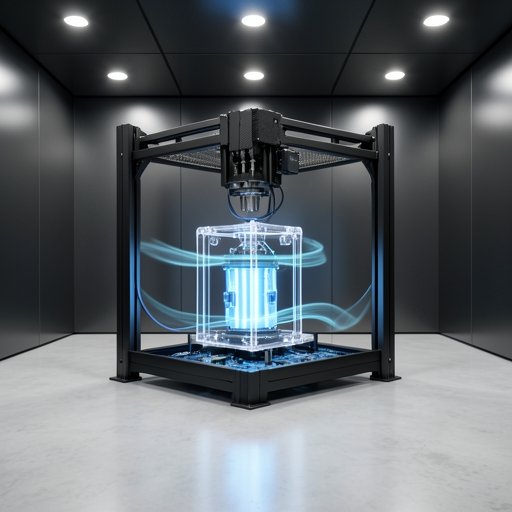
- Liquid Cooling: The gold standard for high-density power. By circulating coolant through channels in the motor housing, you can remove heat directly at the source, allowing the motor to run at much higher continuous torque ratings without over-heating.
Optimizing Surface Area with Specialized Housing Finishes
If using a housed actuator, the exterior finish matters. Anodized surfaces or specialized high-emissivity coatings can improve radiant heat transfer. Incorporating cooling fins into the housing design increases the surface area exposed to ambient air, enhancing natural convection.
Software-Level Strategies to Mitigate Overheating
Your servo drive is your first line of defense against thermal runaway.
Current Limiting and Duty Cycle Optimization
A smart motion control strategy involves “thermal modeling” within the drive. By monitoring the I²t (current squared over time), the drive can predict winding temperature. If the motor approaches its thermal limit, the drive can automatically scale back the peak current or enforce a cooling period (dwell time) in the motion cycle to ensure the average power stays within safe limits.
Leveraging Real-Time Thermal Feedback via Thermistors
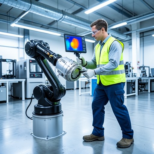
Relying on models is good, but real-time data is better. High-quality motors come equipped with internal thermistors (like KTY or PT100 sensors) embedded in the windings. Integrating this feedback into your safety PLC or motion controller allows for instant emergency stops or cooling fan activation if a temperature spike is detected.
Conclusion: Stability in the Face of Heat
Thermal management is the bridge between a theoretical design and a successful industrial product. By prioritizing heat dissipation during the mechanical design phase and utilizing intelligent current limits in your software, you protect your investment and ensure consistent motor performance.
In the demanding world of modern automation, the most reliable systems are the ones that stay cool under pressure. A well-managed thermal profile leads to longer component life, higher accuracy, and the peace of mind that comes with true system reliability.
FAQ Section: Engineering Heat and Reliability
Q1: What is the maximum safe operating temperature for an HBM series motor?
Our HBM series typically utilizes Class F insulation, which is rated for up to 155°C. However, for maximum longevity and to protect the permanent magnets, we recommend maintaining a continuous winding temperature below 100°C–110°C.
Q2: Does high temperature affect the accuracy of my encoder?
Yes. Most encoders have an operating limit (often around 85°C to 105°C). Beyond this, electronic components can fail or report errors. Furthermore, thermal expansion of the encoder disc can cause small but measurable positioning inaccuracies.
Q3: When is air cooling insufficient for a robotic joint module?
If your application requires the motor to stay at its peak torque for more than 20-30% of the cycle, or if the ambient temperature exceeds 40°C, natural convection and air cooling are often insufficient. In these cases, conductive cooling to a large metal frame or liquid cooling should be considered.