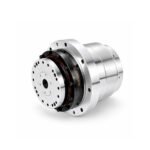
 Joint Rotary Actuators Series HAT
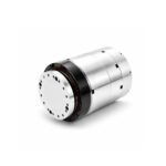 Joint Rotary Actuators series HAS
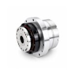 Joint Rotary Actuators Series HAMF
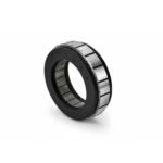 Frameless Torque Motor HBM
 Rotary Actuators
 Joint Rotary Actuators Series HAG
 Rotary Actuators Series HPG
Introduction: The Art and Science of Stable Motion
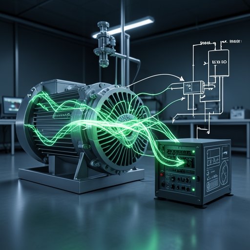
Every commissioning engineer knows the frustrating reality of setting up a new machine: you input the command, you slightly increase the software gain, and suddenly the servo motor begins to scream, vibrate, or aggressively shake the entire mechanical frame.
This happens because the motor’s “brain” is overreacting. The brain behind almost all modern motion control is the PID controller. Understanding how to tame this controller is a rite of passage for automation professionals. While the underlying mathematics are complex, the practical application doesn’t have to be. This guide will demystify PID tuning, providing you with a clear, step-by-step methodology for manual system optimization so your machines run faster, smoother, and quieter.
Deconstructing the PID Loop: What Do the Letters Mean?
PID stands for Proportional, Integral, and Derivative. Think of your motor trying to follow a moving target. The PID loop calculates the “error” (the distance between where the motor is and where it should be) and applies current to fix it.
Proportional (P) Gain: The Driving Muscle
The Proportional gain acts like a virtual spring attached between the motor and the target. If the error is large, the “spring” pulls hard, sending a massive surge of current to close the gap quickly. A higher P-gain makes the system very stiff and highly responsive. However, if the spring is too stiff, the motor will fly past the target (overshoot) and bounce back and forth, causing violent oscillation.
Derivative (D) Gain: The Mechanical Shock Absorber
If P is the spring, the Derivative gain is the shock absorber. The D-gain looks at the rate of change of the error. If the motor is approaching the target too quickly, the D-gain acts as an electronic brake, pushing back against the P-gain to prevent overshoot. It dampens the system, allowing you to use a higher P-gain for speed without causing instability.
Integral (I) Gain: Eliminating Steady-State Error
Even with perfect P and D tuning, a heavy load or friction might cause the motor to stop just a microscopic fraction of a millimeter short of the target. Because the error is so small, the P-gain’s “spring” isn’t pulling hard enough to overcome the friction. The Integral gain looks at the accumulation of error over time. If a tiny error persists, the I-gain slowly builds up power until it forces the motor exactly onto the target, ensuring absolute final accuracy.
A 3-Step Practical Walkthrough for Manual PID Tuning
Before starting, ensure your machine can safely move without hitting physical limits. Always start with very low, conservative values.
Step 1: Start with Zero and Increase the Proportional (P) Gain
Set the I and D gains to zero. Command the motor to make short, rapid, back-and-forth movements (a step response). Slowly increase the P-gain. You will notice the motor becoming more aggressive and tracking the command faster. Keep increasing the P-gain until you hear the motor begin to “ring” or oscillate at the end of the move. Once it becomes unstable, back the P-gain down by about 15% to 20% until the ringing stops.
Step 2: Add Derivative (D) Gain to Stop the Ringing
Now, start slowly increasing the D-gain. As you add damping, the system will become smoother, and any residual ringing from the P-gain should disappear. Because the D-gain stabilizes the system, you can now often go back and increase the P-gain a little more. You will bounce between adjusting P and D until you achieve a very fast, snappy response with absolutely zero oscillation or overshoot.
Step 3: Introduce Integral (I) Gain for Final Accuracy
With your P and D locked in, look at your software scope. You might notice the actual position lags slightly behind the commanded position during the move or fails to settle perfectly at zero error at the end. Slowly increase the I-gain. You will see the steady-state error vanish. However, be careful: too much I-gain introduces a slow, low-frequency “wobble” (instability) into the system. Use just enough to eliminate the error.
Visualizing System Optimization: Reading the Graphs
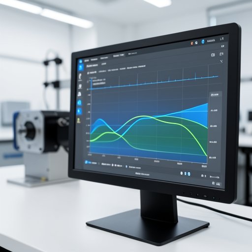
Tuning by ear is a good start, but true system optimization requires analyzing the waveform graphs provided by your servo drive software.
Identifying Overshoot, Undershoot, and Instability
When looking at a step response graph:
- Overshoot: The actual position line flies above the target line before settling back down. This means your P-gain is too high, or your D-gain is too low.
- Sluggish Response (Undershoot): The actual position line takes a long, slow curve to reach the target. Your P-gain is too low, or you have too much D-gain choking the movement.
- Instability: The line looks like a jagged sawtooth wave. The system is vibrating dangerously. Stop the move immediately and reduce the gains.
The Trade-off Between System Stiffness and Smoothness
There is no “perfect” tuning for every application. If you are tuning a CNC machine, you want extremely high stiffness (high P and D) to resist cutting forces, even if it sounds slightly aggressive. If you are tuning a robot handling fragile glass vials, you want a softer, smoother tune to prevent liquid sloshing, accepting a slightly slower response time.
Modern Solutions: When to Use Auto-Tuning
Manual tuning is a vital skill, but modern technology has provided powerful shortcuts.
How Smart Servo Drives Calculate Gains Automatically
Advanced drives, such as modern industrial servo controllers, feature sophisticated Auto-Tuning algorithms. By injecting a high-frequency signal into the motor during a test cycle, the drive automatically calculates the load inertia. It then mathematically derives the optimal P, I, and D parameters instantly, completing in seconds what used to take hours of manual tweaking.
Why Manual Tweaking is Still a Necessary Skill
Auto-tuning assumes the mechanical system is relatively rigid. If your machine uses long belts, flexible couplings, or has severe backlash, the auto-tuner will often fail or generate a highly unstable parameter set. In these real-world scenarios of mechanical compliance, knowing how to manually back off the P-gain or increase the D-gain is the only way to achieve a stable machine.
Conclusion: Mastering the Heartbeat of Your Machine
PID tuning is often seen as dark magic, but it is entirely rooted in physics and logic. By understanding the role of the Proportional “muscle,” the Derivative “damper,” and the Integral “corrector,” you can methodically tame any servo motor.
A well-tuned machine is a joy to observe. It moves with silent, crisp authority, maximizing factory throughput while minimizing mechanical wear. Embrace the software scope, practice the 3-step method, and you will transform from a standard programmer into a true master of motion control.
FAQ Section: Common Servo Tuning Frustrations
Q1: Why does my servo motor make a high-pitched buzzing noise at a standstill?
This is typically caused by the Proportional (P) or Derivative (D) gain being set just at the edge of instability, exciting a high-frequency structural resonance in the machine frame. Slightly lowering the gains, or deploying a “Notch Filter” in the drive software to block that specific frequency, will usually silence the buzzing.
Q2: Do I need to retune my PID loop if the payload weight changes?
Yes. Changing the payload changes the inertia ratio of the system. A PID loop tuned for an empty robot arm will likely perform poorly (or even oscillate violently) when a heavy payload is suddenly attached. For applications with highly variable loads, you must tune for the “worst-case” maximum load scenario to ensure stability.
Q3: What is the difference between tuning the position loop and the velocity loop?
A servo system uses cascaded loops. The Velocity loop is the “inner” loop, controlling how fast the motor spins. The Position loop is the “outer” loop, controlling where it stops. You must always tune the Velocity loop (P and I gains) until it is perfectly stable before you attempt to tune the Position loop (P gain). Tuning them out of order is a recipe for chaos.