 Joint Rotary Actuators Series HAT
 Joint Rotary Actuators series HAS
 Joint Rotary Actuators Series HAMF
 Frameless Torque Motor HBM
 Rotary Actuators
 Joint Rotary Actuators Series HAG
 Rotary Actuators Series HPG
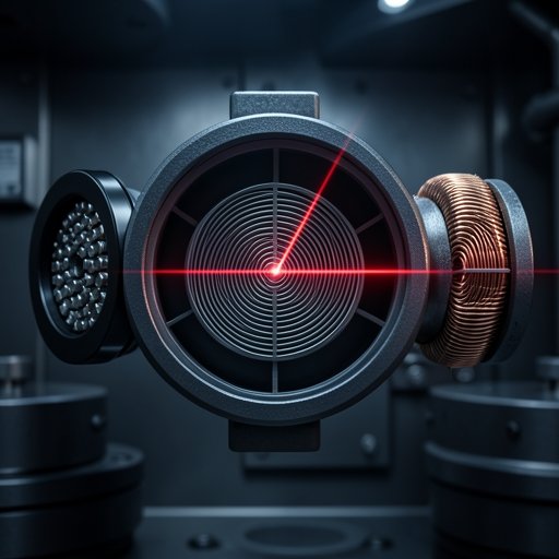
Introduction: The Senses of a Closed-Loop System
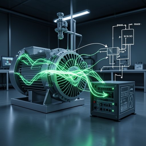
In the world of precision motion control, a motor is merely the “muscle” of the machine, and the servo drive is its “brain.” However, for the brain to precisely control the muscle, it needs “senses.” This is the fundamental definition of a closed-loop servo motor system: it constantly monitors its own output and corrects errors in real-time.
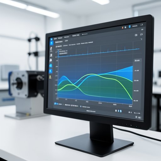
This critical sensory data is provided by position feedback devices. If your feedback device is inaccurate, slow, or fails due to environmental conditions, your entire automation system collapses. Not all feedback sensors are created equal. This guide explores the three main types of feedback devices—optical encoders, magnetic encoders, and resolvers—helping you understand their internal mechanics and how to match them to your specific engineering environment.
Optical Encoders: The Standard for Ultimate Precision
When engineers talk about ultra-high-precision motion, they are almost exclusively referring to systems utilizing optical encoders.
How Light and Glass Discs Measure Rotation
An optical encoder consists of a light source (usually an LED), a rotating disc attached to the motor shaft, and a photodetector. The disc is made of glass or metal and features incredibly fine, etched microscopic transparent and opaque lines. As the motor turns, the light shines through the moving slots, and the photodetector reads the flickering light, converting it into a digital pulse train.
The Advantage of High-Resolution Capabilities
The primary advantage of optical technology is its unparalleled resolution. Modern optical encoders can feature millions of counts per revolution. This extreme density provides the servo controller with highly granular data, allowing for incredibly smooth low-speed motion, rigid holding torque at a standstill, and sub-micron positioning accuracy.
The Vulnerability to Dust, Oil, and High Shock
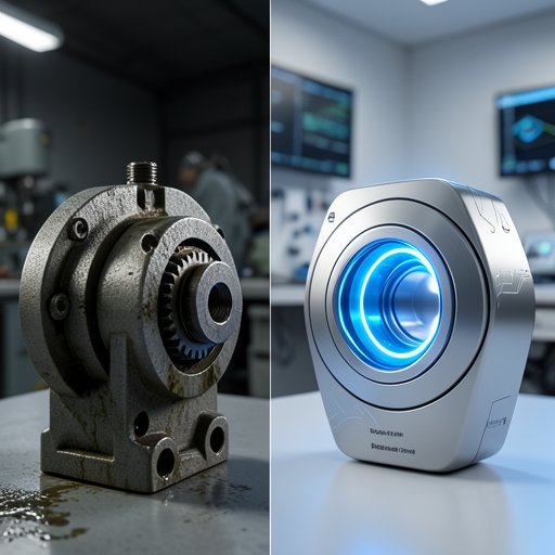
The fatal flaw of the optical encoder is its fragility. Because it relies on the transmission of light, any contamination—such as dust, oil mist, or condensation—that coats the glass disc will “blind” the sensor, leading to immediate drive faults. Additionally, the delicate glass discs can shatter under high mechanical shock or extreme vibration.
Magnetic Encoders: Robust and Reliable
To combat the environmental weaknesses of optical systems, engineers developed the magnetic encoder, bridging the gap between durability and digital precision.
Utilizing Hall-Effect Sensors and Magnetic Poles
Instead of a light and a slotted disc, a magnetic encoder uses a magnetized wheel attached to the motor shaft. This wheel contains alternating north and south magnetic poles. A stationary sensor (often utilizing Hall-effect or magneto-resistive technology) reads the changes in the magnetic field as the wheel spins, translating these fluctuations into digital position data.
Why Magnetic Feedback Excels in Dirty Environments
Magnetic fields are unaffected by dust, dirt, oil, or water. A magnetic encoder will continue to read the shaft position accurately even if the inside of the motor housing is completely contaminated with machining coolant. While historically they offered lower resolution than optical encoders, advanced interpolation electronics have allowed modern magnetic encoders to reach resolutions suitable for highly demanding industrial automation tasks.
Resolvers: The Heavy-Duty Analog Solution
When an application requires survival in environments that would destroy any electronic circuit board, the industry turns to a purely analog, electromechanical solution: the resolver.
What is a Resolver? Analog Transformers in Motion
A resolver is essentially a rotary electrical transformer. It has a primary winding on the rotor and two secondary windings (sine and cosine) on the stator, positioned 90 degrees apart. As the rotor turns, it changes the magnetic coupling between the primary and secondary windings. This induces analog sine and cosine voltage waves. The ratio of these two analog signals gives the exact absolute position of the shaft within one revolution.
Surviving Extreme Heat, Vibration, and Radiation
Because a resolver contains no delicate glass discs, no LEDs, and no onboard sensitive silicon electronics, it is incredibly rugged. It is just copper wire and steel laminations. Resolvers can operate flawlessly in extreme temperatures (often exceeding 150°C to 200°C), survive massive shock and vibration, and even withstand high levels of radiation.
The Trade-off: Lower Precision and Digital Conversion Needs
The trade-off for this indestructibility is complexity in the drive. The analog signals from the resolver must be converted into digital data using a Resolver-to-Digital (R/D) converter inside the servo drive. Generally, the resulting digital resolution is lower than that of high-end optical encoders, meaning a resolver-based system might not be as perfectly smooth at very low speeds or as pinpoint-accurate in high-precision CNC applications.
Application Guide: Choosing the Right Position Feedback
Selecting the right device is a matter of evaluating your machine’s operating environment and its precision requirements.
Best for CNC and Robotics: Optical Encoders
If you are designing a 5-axis CNC machine, a laser cutting bed, or a collaborative robot arm where sub-micron accuracy and smooth path contouring are paramount, optical encoders are the gold standard. You must, however, ensure the motor housing is adequately sealed (high IP rating) to protect the sensor.
Best for Mobile Robots and General Automation: Magnetic Encoders
For Automated Guided Vehicles (AGVs), packaging machinery, and textile equipment where the environment might be dusty or subject to moderate vibration, magnetic encoders provide the perfect balance. They offer excellent digital resolution while remaining highly resistant to typical factory floor contamination.
Best for Aerospace and Heavy Metallurgy: Resolvers
If your motor is operating inside a hot steel mill, mounted on an oil drilling rig, or used in aerospace flight control surfaces, resolvers are the only choice. When failure is not an option and the environment is extreme, the robust, analog nature of the resolver guarantees that you will not lose position data.
Conclusion: Matching the Sensor to the Environment
There is no single “best” servo motor feedback device. The choice is a deliberate engineering trade-off between the ultimate precision of optical systems, the resilient balance of magnetic systems, and the heavy-duty survivability of analog resolvers.
By carefully analyzing the vibration, temperature, contamination levels, and accuracy targets of your specific application, you can select the right position feedback technology. Ensuring your motor has the correct “senses” is the foundation of building a reliable, high-performance automation system. Hobber Drive understands this critical balance, designing motors and actuators with tailored feedback options to suit any industrial challenge.
FAQ Section: Feedback Device Troubleshooting
Q1: Can a servo drive process signals from both an encoder and a resolver?
It depends entirely on the drive’s hardware. Encoders output digital signals (like RS-422 pulses or serial data protocols), while resolvers output analog sine/cosine waves. A drive must have a specific Resolver-to-Digital (R/D) expansion card or built-in circuitry to read a resolver.
Q2: How does temperature affect an optical encoder compared to a resolver?
Optical encoders have strict thermal limits (often 85°C to 105°C) because high heat can damage the onboard LEDs and silicon photodetectors, or cause thermal expansion that misaligns the optical mask. Resolvers, being made of wire and steel, are virtually immune to standard industrial temperature fluctuations.
Q3: What is the difference between a feedback device and an external linear scale?
A feedback device (encoder/resolver) is mounted directly on the motor shaft, measuring the motor’s rotation. An external linear scale is mounted directly on the moving machine part (like a CNC table). The linear scale provides “full closed-loop” feedback, compensating for any mechanical backlash or belt stretch between the motor and the final load, offering the highest possible system accuracy.