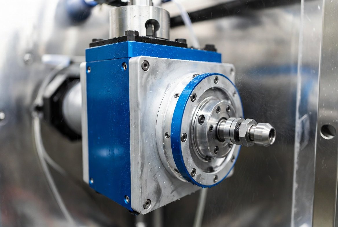
 Joint Rotary Actuators Series HAT
 Joint Rotary Actuators series HAS
 Joint Rotary Actuators Series HAMF
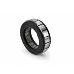 Frameless Torque Motor HBM
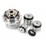 Rotary Actuators
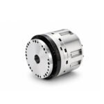 Joint Rotary Actuators Series HAG
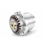 Rotary Actuators Series HPG
Introduction: The Trap of Peak Ratings in Motion Sizing
In the excitement of designing a new machine, engineers often fall into a dangerous trap: they look at a motor’s peak torque rating, see that it exceeds their application’s requirement, and check the component off their list. Hours later, on the factory floor, that same motor triggers a thermal overload fault or burns out completely within weeks of deployment.
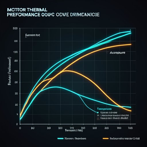
Why does this happen? Because raw power is only half the equation. The missing variable is time. In high-frequency automation, understanding how a motor handles heat over a repeating work cycle is just as important as knowing its maximum output. This critical metric is known as the duty cycle. Mastering duty cycle analysis and effective thermal management are the cornerstones of accurate motor selection and long-term system reliability.
What is Motor Duty Cycle? (S1 Through S8 Explained)
In electrical engineering, duty cycle refers to the ratio of operating time to the total time of a complete repeating cycle. International standards (IEC 60034-1) categorize motor duty types from S1 to S8 to define how machines handle thermal loads.
Continuous Duty (S1): The 100% Run-Time Baseline
An S1 rating means the motor can run continuously at its rated load 24/7, reaching a stable thermal equilibrium where the heat generated equals the heat dissipated into the environment. This is typical for simple conveyors or continuous spindles.
Intermittent Duty (S3–S8): The Reality of Pick-and-Place and Indexing
Most modern automation—such as pick-and-place gantries, robotic joints, and indexing tables—operates under intermittent duty cycles (S3 through S8). These machines accelerate, decelerate, pause, and reverse. Because the motor is not running at 100% capacity all the time, it gets periodic “rest” intervals. These rest periods allow the internal windings to cool down, meaning you can often push a smaller motor to higher torque peaks than its continuous S1 rating would otherwise allow—provided you calculate the thermal limits correctly.
The Physics of Heat: Why Rest Periods Matter as Much as Run Times
To understand why intermittent systems can handle higher peaks, you must look at the thermodynamic properties of electric motors.
Copper Losses (I2RI2R) and Thermal Time Constants
Heat inside a motor is primarily generated by electrical resistance in the copper windings (
I2RI2Rlosses). When current flows, temperature rises exponentially, governed by the motor’s “Thermal Time Constant.” This constant represents how long it takes for the motor to reach roughly 63% of its final steady-state temperature.
How Thermal Equilibrium Dictates Safe Operation
If an acceleration phase pumps heat into the motor faster than it can escape, the temperature climbs. During the dwell or rest period, the heat begins to dissipate into the housing and surrounding air. Safe operation means ensuring the peak temperature during the work phase never exceeds the insulation class limit (such as 155°C for Class F insulation) before the cooling phase brings it back down.
Calculating RMS Torque for Complex Motion Profiles
Guessing a duty cycle is a recipe for failure. Sizing requires mathematical precision through Root Mean Square (RMS) calculations.
Breaking Down Acceleration, Dwell, and Return Strokes
A complex motion profile consists of multiple distinct segments: acceleration, constant velocity, deceleration, and dwell (rest). Each segment generates a specific amount of torque and heat. To find the true thermal load, you cannot simply average these values linearly.
Using Equivalent RMS Formulas for Accurate Motor Sizing
Engineers use the RMS torque formula to distill a complex, fluctuating motion cycle into a single equivalent continuous torque value:
Trms=T12⋅t1+T22⋅t2+⋯+Tn2⋅tnttotalTrms=ttotalT12⋅t1+T22⋅t2+⋯+Tn2⋅tnThe resulting
TrmsTrmsmust fall well within the motor’s continuous torque rating. If your RMS torque calculation is higher than the motor’s continuous rating, the motor will eventually overheat, regardless of how short the peak bursts are.
Practical Design Strategies to Improve Thermal Performance
If your calculations show that your motor is running too hot for a given duty cycle, you have several engineering paths to improve thermal performance.
Optimizing Motion Trajectories to Reduce Peak Current
Often, smoothing out the motion profile can dramatically drop thermal stress. By replacing abrupt trapezoidal moves with S-curve trajectories, you lower peak acceleration spikes. Because current is proportional to torque, reducing peak acceleration significantly cuts down on
I2RI2Rcopper losses.
Enhancing Conduction Paths via Actuator Housing Design
Thermal management is heavily dependent on mechanical integration. Mounting a frameless motor directly into a massive aluminum machine frame provides an incredible thermal sink, drawing heat away from the stator coils much faster than free-standing ambient air ever could.
Conclusion: Sizing Smart, Running Cool
The duty cycle is the bridge between mechanical demand and thermal reality. Ignoring it leads to premature component degradation, unexpected thermal shutdowns, and costly downtime on the factory floor.
By taking the time to calculate RMS torque and understanding how your application’s work-to-rest ratio affects internal temperatures, you ensure your equipment operates within safe physical limits. Proper thermal management and rigorous motor selection guarantee that your automation systems deliver the dependable, long-term system reliability your customers demand.
FAQ Section: Motor Sizing and Duty Cycle Q&A
Q1: How does ambient temperature affect a motor’s rated duty cycle?
Ambient temperature dictates your starting baseline. If a motor is rated for a specific duty cycle at 25°C ambient, placing it inside a hot enclosure or a 45°C factory environment reduces its ability to shed heat. You must “de-rate” the motor’s continuous capacity as ambient temperatures rise.
Q2: Can I run an S1 continuous motor intermittently at much higher torque?
Yes, up to a point. Because an S1 motor is designed to dissipate heat continuously, it often has good thermal mass. However, you must still verify that the peak current does not saturate the magnetic core or exceed the mechanical strength of the bearings and gearbox. Always use the RMS calculation to confirm.
Q3: What is a thermal time constant, and where do I find it on a Hobber datasheet?
The thermal time constant (often denoted as
τthτth) tells you how quickly a motor heats up or cools down. It defines the time required to reach ~63% of its final temperature change. This specification is typically found in the advanced technical documentation of our product datasheets, helping engineers model transient thermal behavior during extreme custom cycles.