 Joint Rotary Actuators Series HAT
 Joint Rotary Actuators series HAS
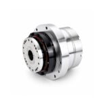 Joint Rotary Actuators Series HAMF
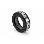 Frameless Torque Motor HBM
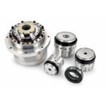 Rotary Actuators
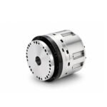 Joint Rotary Actuators Series HAG
 Rotary Actuators Series HPG
Introduction: When Motors Become Generators
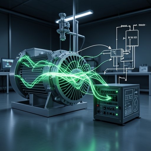
In the mechanics of motion control, we typically think of electricity flowing in one direction: from the power grid, through the servo drive, and into the motor to create physical movement. However, physics dictates that energy cannot be created or destroyed—it can only change form.
What happens when a high-inertia axis decelerates rapidly, or when a vertical gantry lowers a heavy load against gravity? That stored kinetic or potential energy has to go somewhere. Instead of absorbing power, the motor temporarily transforms into a generator, pushing electrical energy back into the drive system.
This phenomenon is known as regenerative braking. Mastering how to handle this returned energy is a crucial aspect of designing a reliable servo drive architecture, protecting hardware from catastrophic damage, and driving overall energy efficiency in modern manufacturing.
The Physics of Regeneration: Back-EMF and the DC Bus
To understand why regeneration happens, we must look at the electromagnetic forces inside the motor during a slowdown event.
How Deceleration Turns Kinetic Energy into Electrical Power
A permanent magnet servo motor works on the principle of electromagnetic induction. When you supply current, it creates motion. Conversely, when the mechanical load forces the motor to spin faster than the commanded electrical field—or when the controller commands a rapid stop—the rotor magnets continue spinning past the stator coils. This induces a voltage in the windings known as Back-EMF (Electromotive Force). If this generated voltage exceeds the drive’s internal operating voltage, the motor becomes a generator, converting kinetic energy back into electrical current.
The Danger of DC Bus Overvoltage in Servo Amplifiers
This generated current flows backward into the servo drive, rushing directly into the internal DC bus capacitors. If the energy input is greater than what the capacitors can absorb, the DC bus voltage spikes. If this voltage crosses a critical safety threshold, the drive will instantly trigger an “Overvoltage Fault” and shut down to protect its sensitive electronics, resulting in an abrupt, uncontrolled machine stop.
Traditional Energy Dissipation: The Braking Resistor
For decades, the standard method for dealing with this surplus energy has been passive thermal dissipation.
How Dynamic Braking Resistors Burn Off Excess Energy as Heat
To prevent DC bus overvoltage, servo drives are equipped with a transistor switch (often called a chopper transistor) and an external or internal component known as a braking resistor. When the drive detects that the DC bus voltage is rising too high, it opens the switch, diverting the excess electrical energy into the resistor. The resistor converts the electrical power into waste heat, which is then vented into the cabinet air.
The Limitations: Thermal Waste and Cabinet Cooling Challenges
While dynamic braking resistors are simple and reliable, they represent a significant waste of energy. Furthermore, burning off kilowatts of power inside a sealed electrical control cabinet creates a massive thermal management challenge. This often forces engineers to install expensive air conditioners or cooling fans just to manage the heat generated by the braking resistors alone.
Modern Regeneration: Pushing Power Back to the Grid
As industries push toward stricter sustainability goals and lower operating costs, passive heat dissipation is increasingly seen as an inefficient relic of the past.
Active Energy Recovery vs. Passive Dissipation
Advanced power electronics have enabled active regenerative drives. Instead of burning excess energy as heat through a resistor, an active front-end (AFE) inverter captures the returned current, conditions it back into clean AC power, and feeds it directly back into the facility’s main electrical grid.
Driving Industrial Sustainability Through Intelligent Power Management
In applications involving heavy, frequent vertical movements—such as heavy industrial elevators, automated storage and retrieval systems (AS/RS), or large stamping presses—regenerative power management can reduce a facility’s total electricity consumption by up to 20% to 30%. This dramatic boost in energy efficiency aligns perfectly with corporate environmental mandates and significantly trims long-term utility bills.
Sizing and Protecting Your System Against Overvoltage Faults
Whether you are using traditional resistors or advanced feedback systems, proper sizing is mandatory.
Calculating Peak Regenerative Power in High-Inertia Axes
To size your braking system correctly, you must calculate the maximum kinetic energy stored in your moving load (
Ek=12Jω2Ek=21Jω2). You then divide this energy by the deceleration time to find the peak regenerative power. Your drive and its braking hardware must be capable of handling this surge without tripping.
Best Practices for Common DC Bus Sharing in Multi-Axis Machines
In multi-axis machines, one axis is often accelerating (consuming power) while another is decelerating (generating power). By tying the DC buses of multiple servo drives together on a common bus bar, the energy generated by the braking axis can be instantly consumed by the accelerating axis. This internal energy sharing minimizes waste and reduces the need for external braking resistors altogether.
Conclusion: Smart Energy Management for Smarter Factories
Regenerative braking is a powerful reminder that in motion control, energy is a two-way street. Managing the electrical power pushed back into your system during deceleration is vital for protecting your hardware from overvoltage faults and ensuring seamless operation.
Whether through carefully sized dynamic resistors or advanced energy-recovery grids, smart power handling reduces thermal stress, slashes utility costs, and drives true sustainability on the factory floor. By understanding and implementing proper regenerative braking strategies, engineers can build motion systems that are as efficient as they are precise.