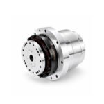
 Joint Rotary Actuators Series HAT
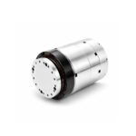 Joint Rotary Actuators series HAS
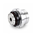 Joint Rotary Actuators Series HAMF
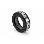 Frameless Torque Motor HBM
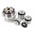 Rotary Actuators
 Joint Rotary Actuators Series HAG
 Rotary Actuators Series HPG
Introduction: The Geometry of Metal Cutting
In the world of precision manufacturing, a CNC machine is like a high-stakes dancer. Every move must be calculated, synchronized, and perfectly executed to transform a raw block of metal into a complex component. The science behind this “dance” is known as kinematics.
Technically, kinematics is the study of motion without considering the forces that cause it. In the context of CNC machine tools, kinematics describes how the various axes of the machine move and interact to place the cutting tool at the exact point in space required by the part program. Understanding these motions is key to mastering 5-axis machining. Let’s break down the evolution of machine motion from the ground up.
The Foundation: 3-Axis Cartesian Kinematics
The vast majority of CNC machines start with the Cartesian coordinate system—the same XYZ grid you likely learned in high school geometry.
The XYZ Orthogonal System
In a standard 3-axis mill, the machine has three linear axes:
- X-Axis: Typically left-to-right movement.
- Y-Axis: Typically front-to-back movement.
- Z-Axis: Up-and-down movement (usually the spindle axis).
These axes are orthogonal, meaning they are at 90-degree angles to each other. By moving these three axes simultaneously, the machine can reach any point within its cubic work envelope.
Limitations of Linear-Only Motion
While 3-axis machines are workhorses, they have a major limitation: the tool always remains vertical (or horizontal, depending on the machine type). To machine the underside or the side of a part, you must manually stop the machine, rotate the part, and set up a new operation. This introduces setup errors and increases production time.
Adding the First Rotary Axis: 4-Axis Machining
To overcome the limitations of 3-axis motion, engineers introduced the rotary axis. This adds a new level of freedom to the machine’s kinematics.
Understanding the A or B Axis
In a 4-axis machine, a rotary table is added to the machine bed. This axis is usually named according to the linear axis it rotates around:
- A-Axis: Rotation around the X-axis.
- B-Axis: Rotation around the Y-axis.
Common Applications for 4th Axis Rotary Tables
The addition of a 4th axis allows the machine to rotate the part while the tool is cutting. This is essential for machining cylindrical parts, cutting helical gears, or simply rotating a block to machine four sides in a single setup. It is the first step toward true multi-axis complexity.
The Pinnacle of Flexibility: 5-Axis Machining
When you add a second rotary axis, you enter the world of 5-axis machining. This configuration allows the tool to approach the workpiece from virtually any angle, enabling the creation of complex, organic shapes like turbine impellers or medical implants.
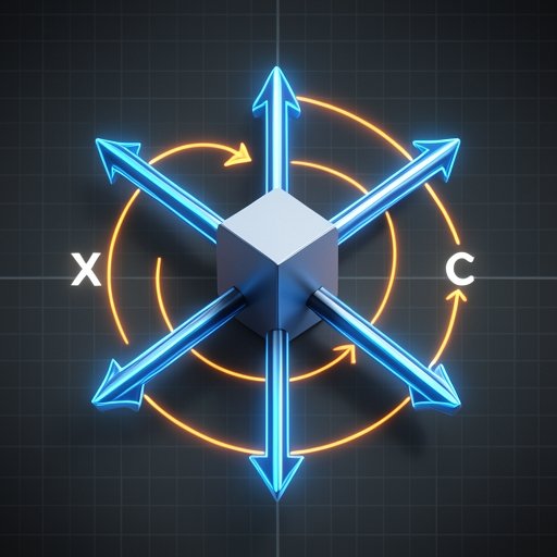
Defining the A, B, and C Rotary Axes
A 5-axis machine uses three linear axes (X, Y, Z) and two of the three possible rotary axes:
- A-Axis: Rotation around X.
- B-Axis: Rotation around Y.
- C-Axis: Rotation around Z.
Common Configurations: Trunnion vs. Swivel Head
There are two primary ways to achieve 5-axis motion:
- Trunnion Style: The machine table tilts and rotates (A and C axes). The tool stays stationary in its orientation. This is great for heavy parts and large work envelopes.
- Swivel Head Style: The spindle itself tilts and rotates. This is often preferred for very large parts where moving the workpiece is impractical.
The Benefit of Simultaneous 5-Axis Motion
The real power lies in “simultaneous” motion, where all five axes move at once. This allows the tool to stay perfectly perpendicular to a curved surface throughout a cut, resulting in superior surface finishes and much faster machining times.
Why Rotary Axis Precision is the Bottleneck of Kinematics
As you increase the complexity of the kinematics, the mechanical quality of the rotary axis becomes the deciding factor in part quality.
The Multiplier Effect of Angular Errors
In a linear axis, an error of 0.01mm is just 0.01mm. However, in a rotary axis, an angular error of just a fraction of a degree is multiplied by the length of the tool or the part. A tiny deviation at the center of rotation can result in a massive gouge at the edge of a large part.
Achieving Smooth Contouring with High-Performance Actuators
To handle the complex math of 5-axis contouring, the rotary axes must be incredibly responsive and free of backlash. This is why high-performance CNC machines rely on specialized actuators—like those from Hobber Drive—that provide the high torsional stiffness and zero-backlash performance required to keep the “dance” of the axes perfectly in sync.
Conclusion: Mastering the Motion of Tomorrow
Understanding the kinematics of your machine tool is about more than just knowing which way the table moves. It is about understanding the limitations of your hardware and how multi-axis coordination can unlock new manufacturing possibilities.
As the industry moves toward more complex parts and tighter tolerances, the role of high-precision rotary motion will only grow. Whether you are operating a simple 3-axis mill or a state-of-the-art 5-axis center, the quality of your motion is the foundation of your success.
FAQ Section: CNC Kinematics Basics
Q1: What is the difference between 4+1 and full 5-axis machining?
In 4+1 (or “positional” 5-axis), the two rotary axes move the part to a specific angle and then lock in place while the 3 linear axes do the cutting. In “full” or simultaneous 5-axis, all five axes move continuously during the cutting process.
Q2: How are the names (A, B, C) of the rotary axis determined?
The industry standard dictates that A rotates around X, B rotates around Y, and C rotates around Z. The direction of rotation follows the “Right-Hand Rule” relative to the positive direction of the linear axis.
Q3: Does adding more axes reduce the rigidity of the machine?
Technically, yes. Every “joint” added to a machine introduces a potential point of deflection. This is why high-quality 5-axis machines use exceptionally rigid rotary actuators and heavy-duty castings to compensate for the added complexity.