 Joint Rotary Actuators Series HAT
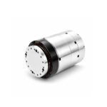 Joint Rotary Actuators series HAS
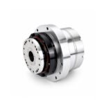 Joint Rotary Actuators Series HAMF
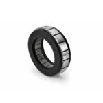 Frameless Torque Motor HBM
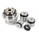 Rotary Actuators
 Joint Rotary Actuators Series HAG
 Rotary Actuators Series HPG
Introduction: The Force That Drives Automation
In the realm of industrial automation, we often get caught up in discussions about advanced communication protocols, high-resolution encoders, and complex servo tuning algorithms. However, beneath all the software and electronics, motion control is governed by strict, immutable laws of physics. At the very center of these laws is one critical concept: motor torque.
Whether you are sizing a tiny robotic joint or a massive CNC rotary table, torque is the fundamental twisting force that makes motion possible. Misunderstanding its principles leads to undersized motors, overheating, and mechanical failure. This guide serves as a refresher on the engineering basics of torque, exploring how it relates to power and speed, and laying the groundwork for accurate torque calculation in your next project.
What is Torque? The Fundamental Equation
In linear motion, a force pushes or pulls an object in a straight line. In rotational motion, torque is the equivalent concept—it is a force that causes an object to rotate around an axis.
The Cross Product of Force and Radius
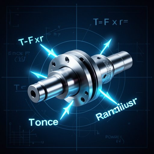
The fundamental physics equation for torque (
ττ) is the cross product of the force vector (
FF) and the distance vector (
rr) from the axis of rotation (the lever arm). In a simplified, perpendicular system, this is expressed as:
Torque=Force×RadiusTorque=Force×Radius(
T=F×rT=F×r)
If you apply a 10 Newton force at the end of a 1-meter wrench, you generate 10 Newton-meters (Nm) of torque. If you shorten the wrench to 0.5 meters, you must apply twice the force (20 Newtons) to achieve the same 10 Nm of torque.
Units of Measurement in Motion Control
In the international engineering community, motor torque is universally measured in Newton-meters (Nm). While you may occasionally encounter Imperial units like pound-inches (lb-in) or ounce-inches (oz-in), converting them to Nm is essential for standardized torque calculation when matching motors to modern metric gearboxes and actuators.
The Relationship Between Torque, Speed, and Mechanical Power
A common point of confusion in engineering basics is the difference between torque and power. A motor can produce massive torque but generate zero power if it is not moving.
Power is Torque in Motion
Mechanical power is the rate at which work is done. In a rotational system, power (
PP) is the product of torque (
TT) and angular velocity (
ωω):
Power=Torque×SpeedPower=Torque×SpeedThis equation dictates a fundamental trade-off in motor sizing. For a motor with a fixed maximum power output, you can either have high speed and low torque, or low speed and high torque. You cannot have both simultaneously without increasing the physical size and electrical power rating of the motor.
The Role of the Gearbox as a Transformer
This power equation explains why we use precision gearboxes. A gearbox acts as a mechanical transformer. By reducing the speed (angular velocity) by a factor of 10, a 10:1 planetary or strain wave gear multiplies the input motor torque by a factor of 10 (minus a small loss for mechanical efficiency). The total mechanical power remains relatively constant, but it is reshaped into a highly useful, high-torque format for robotic lifting.
Static Torque vs. Dynamic Torque
When performing a torque calculation for a servo system, engineers must evaluate two different physical states: static and dynamic.
Static (Holding) Torque: Fighting Gravity
Static torque is the force required to hold a load steady against external forces, most commonly gravity. If a robotic arm is holding a 5kg weight straight out horizontally, the motor must supply continuous static torque to prevent the arm from falling. This generates continuous heat in the motor coils without doing any actual “work” (because the speed is zero).
Dynamic (Acceleration) Torque: Overcoming Inertia
Dynamic torque is governed by Newton’s Second Law of Rotation:
Torque=Inertia×AngularAccelerationTorque=Inertia×AngularAcceleration(
T=J×αT=J×α).
To change the speed of a load, you must overcome its moment of inertia. The faster you want a robotic joint to accelerate, the more dynamic torque the motor must supply. In high-speed automation, the dynamic torque required for rapid start-stop cycles is often significantly higher than the static torque required to hold the load.
How Motor Design Generates Electromagnetic Torque
In an electric motor, torque is not generated by a physical wrench, but by the Lorentz force—the interaction between an electric current and a magnetic field.
The Air Gap and Rotor Diameter
The torque produced by a permanent magnet motor is proportional to the magnetic flux, the current in the stator coils, and crucially, the radius of the air gap between the stator and the rotor.
This explains why frameless torque motors are designed with a “pancake” shape—a large outer diameter and a short axial length. By maximizing the radius (
rr) at which the electromagnetic force (
FF) is applied, frameless motors naturally generate exceptionally high motor torque density without requiring mechanical gearing.
Conclusion: Physics as the Ultimate Design Tool
In the fast-paced world of machine design, it is easy to rely on sizing software and automated calculators. However, a deep understanding of the engineering basics behind motor torque is what separates a good engineer from a great one.
By remembering that torque is a function of force and radius, and that power is the balance of torque and speed, you can critically evaluate mechanical designs, troubleshoot sluggish servo responses, and execute your next torque calculation with absolute confidence. The physics will never lie to you; mastering them is the first step to mastering precision motion control.