 Joint Rotary Actuators Series HAT
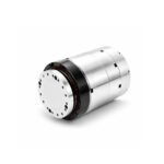 Joint Rotary Actuators series HAS
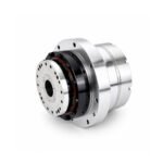 Joint Rotary Actuators Series HAMF
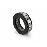 Frameless Torque Motor HBM
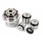 Rotary Actuators
 Joint Rotary Actuators Series HAG
 Rotary Actuators Series HPG
Introduction: The Hidden Physics Behind Servo Instability
Every engineer who has commissioned a motion system has faced the “tuning nightmare.” You have a high-quality motor and a powerful drive, yet the moment you increase the gains, the system starts to hum, vibrate, or even shake violently. Often, the culprit is not the software or the wiring—it is the hidden physics of load inertia.
In motion control, inertia is the resistance of a physical object to any change in its velocity. While it sounds simple in a textbook, in a real-world servo system, the relationship between the motor’s internal inertia and the load it carries is the primary factor governing stability. This guide will explore why mastering load inertia is essential for achieving peak system performance and effortless servo tuning.
What is Load Inertia? More Than Just Weight
A common misconception is that “heavy” objects have high inertia. While mass is a factor, in rotational motion, where that mass is distributed matters much more.
The Moment of Inertia in Rotational Systems
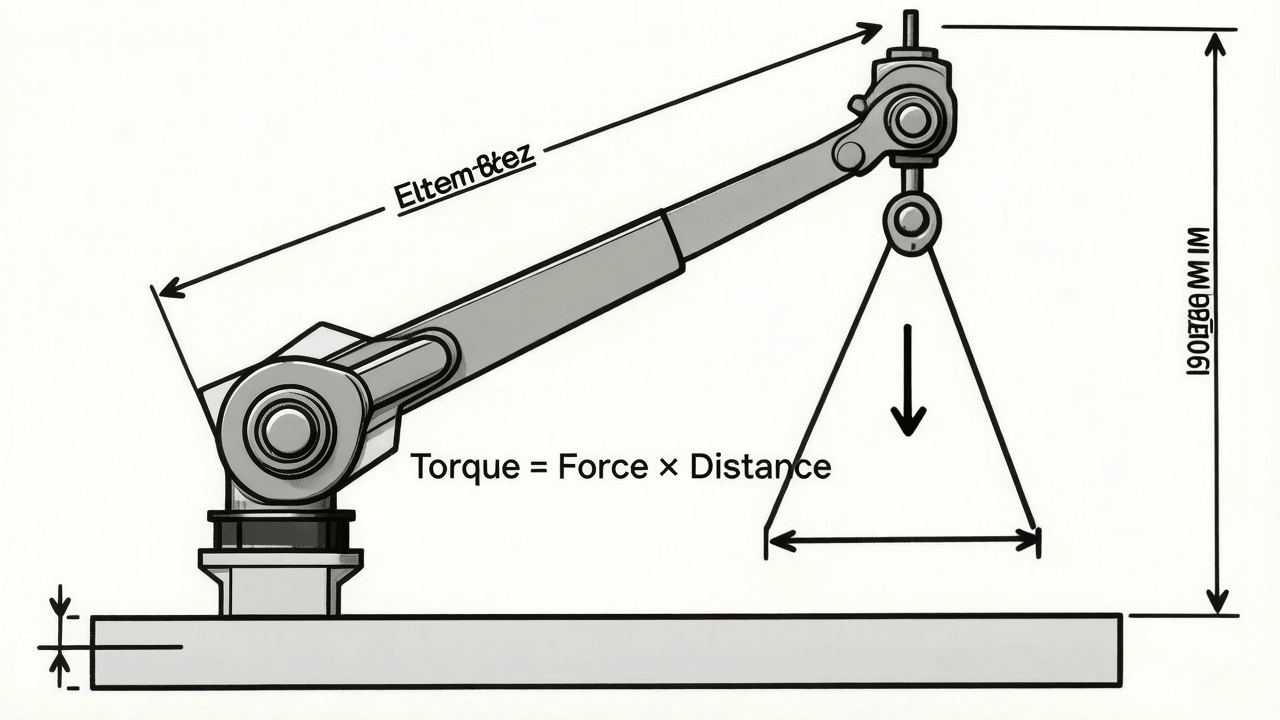
The load inertia (specifically the Moment of Inertia) measures how difficult it is to change the rotational speed of an object. For a rotating mass, the formula is generally. This means that the distance from the center of rotation (the radius) has a squared effect on the inertia.
Why the Radius Matters More Than the Mass
If you double the mass of a load, you double the inertia. However, if you move that same mass twice as far from the shaft, you quadruple the inertia. This is why a small sensor mounted at the end of a long robot arm can create more “tuning headaches” than a heavy gearbox mounted directly to the motor.
The Critical Ratio: Inertia Matching for Stability
In a servo system, the drive is constantly calculating how much current to send to the motor to keep it on its commanded path. The success of this calculation depends on the “Inertia Ratio.”
Defining the Inertia Ratio (Jload/JmotorJload/Jmotor)
The inertia ratio is the value of the reflected load inertia divided by the motor’s own rotor inertia. If the ratio is 1:1, the motor and load are perfectly matched, and control is easy. However, as the ratio increases, the load begins to “boss” the motor around, making it harder for the controller to stay in charge.
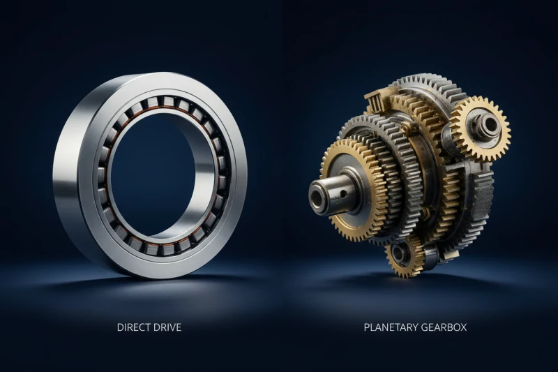
The 10:1 Rule: When Do You Need a Gearbox?
As a general rule of thumb in high-performance automation, an inertia ratio of 10:1 or lower is considered ideal. Once you exceed 20:1 or 30:1, the system becomes significantly harder to tune. If your load is massive, you must use a precision gearbox. A gearbox with a ratio of reduces the reflected inertia by, bringing a difficult 100:1 load down to a manageable 1:1 ratio.
How Inertia Impacts Servo Tuning and Response
When your inertia ratio is mismatched, your servo tuning options become limited, directly impacting your machine’s productivity.
Dealing with Resonance and High-Frequency Jitter
High load inertia acts as a mechanical spring. When the motor tries to stop, the load “winds up” the coupling or the gear teeth and then snaps back. This creates mechanical resonance. To stop the resulting jitter, engineers often have to lower the “Velocity Loop Gain,” which unfortunately makes the robot move slower and less accurately.
The Trade-off Between Settling Time and Overshoot
A high-inertia system is like a heavy ship; it takes a long time to start moving and a long time to stop. If you tune the system for a fast response, you will likely see “overshoot,” where the motor flies past its target and has to correct itself. This increases “settling time,” the delay before the machine can perform its next task.
Advanced Solutions: How Modern Drives Handle Mismatched Inertia
At Hobber Drive, we design our hardware to help engineers overcome these physical limitations.
Leveraging Auto-Tuning Algorithms in GSHD Drives
Modern digital drives, like our GSHD series, include advanced auto-tuning routines. These drives can automatically estimate the load inertia by performing small, rapid test moves. Once the drive knows the real-world inertia ratio, it automatically adjusts its internal PID loops to provide the highest possible gain without causing vibration.
Using Notch Filters to Suppress Mechanical Resonance
When a high inertia ratio excites a specific frequency in your machine frame, a “Notch Filter” can be used. This is a software filter within the servo drive that “ignores” that specific vibration frequency, allowing you to keep your gains high and your response fast, even in less-than-ideal mechanical conditions.
Conclusion: Balancing Mechanics and Control for Success
Achieving high-performance motion is a partnership between mechanical design and electronic control. While modern servo drives can compensate for many challenges, they cannot break the laws of physics.
By calculating your load inertia during the design phase and selecting a motor or actuator with an appropriate inertia ratio, you set your project up for success. Remember: a stiff, well-matched mechanical system is always easier to tune than a flexible, mismatched one.
FAQ Section: Expert Advice on Inertia Management
Q1: Does a hollow rotary actuator reduce reflected inertia? Actually, the actuator itself adds a small amount of internal inertia. However, because our hollow rotary actuators often include high-reduction precision gearing, they are excellent at reducing the reflected inertia of the external load, making the system much more stable.
Q2: Can I run a system with a 50:1 inertia ratio? Yes, but it requires a very high-quality drive (like the GSHD series) and expert tuning. You will likely have to sacrifice some dynamic performance (acceleration) to maintain stability. For precision tasks, we recommend keeping the ratio below 15:1.
Q3: How do I measure my actual load inertia without a CAD model? Most Hobber Drive servo software has an “Inertia Identification” function. By letting the motor spin the uncoupled load in a controlled test, the drive can calculate the inertia based on the torque required to achieve a specific acceleration.