 Joint Rotary Actuators Series HAT
 Joint Rotary Actuators series HAS
 Joint Rotary Actuators Series HAMF
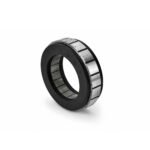 Frameless Torque Motor HBM
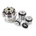 Rotary Actuators
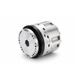 Joint Rotary Actuators Series HAG
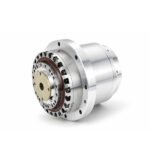 Rotary Actuators Series HPG

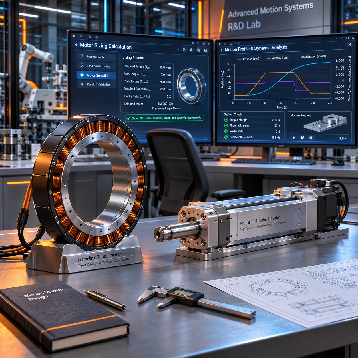
Introduction: Beyond Static Weight – The Reality of Dynamic Motion
In the exciting phase of designing a new machine, engineers often make a critical assumption during the initial component selection phase: they calculate the static weight of a load, look for a motor that matches that holding torque, and assume the job is done. Hours later, on the test bench, that same motor overheats, struggles to hit target speeds, or fails to stop accurately.
Why? Because static weight only tells half the story. The real test of an industrial machine happens during rapid acceleration, deceleration, and high-frequency reversals—what engineers call high-dynamics. Mastering motor sizing for high-dynamic applications is the difference between a sluggish, failing prototype and a high-performance, lightning-fast automation system. This guide breaks down the foundational engineering steps required to size motors for intense dynamic loads.
What Makes an Application “Dynamic”?
In motion control, an application is considered “dynamic” when the forces required to change the speed and direction of the load significantly outweigh the forces required to hold it against gravity.
High-Frequency Start-Stop Cycles and Rapid Reversals
Consider a high-speed pick-and-place gantry or an electronic component inserter. These machines do not cruise at a steady speed; they explode into motion, race across a workspace, and brake aggressively, sometimes reversing direction dozens of times a minute. Every single one of these transitions forces the motor to fight the physical laws of inertia.
The Dominance of Acceleration Torque Over Static Gravity
In high-dynamic systems, acceleration torque easily dwarfs static load torque. While gravity might demand 5 Nm of holding torque, the act of accelerating a heavy payload from zero to 3,000 RPM in 0.1 seconds might require 50 Nm of peak torque. If your motor sizing only accounts for the static phase, the motor will stall or trigger immediate over-current errors the moment it tries to move.
Step 1: Defining the Motion Profile and Kinematics
The first step in any rigorous sizing process is translating physical machine movements into a mathematical motion profile.
Mapping Out Displacement, Velocity, and Time
You must map out every phase of the movement cycle: the dwell time (rest), the acceleration phase, the constant velocity cruise (if any), and the deceleration phase. Plotting position versus time and velocity versus time gives you a clear picture of the peak velocities and the time intervals available to complete each move.
Calculating Peak and Continuous Acceleration Rates
From your velocity profile, you calculate the required acceleration rate (
αα). The steeper the slope of your velocity curve, the higher the acceleration—and the greater the torque required from your motor. This kinematic baseline forms the foundation for all subsequent electrical and mechanical calculations.
Step 2: Torque Calculation for Dynamic Loads
With your motion profile defined, you can calculate the two critical torque figures needed for successful motor selection.
Factoring in Payload Inertia and Drivetrain Mass
To calculate acceleration torque, you must determine the total system inertia (
JtotalJtotal), which includes the motor rotor, couplings, gearboxes, mechanical stages, and the payload itself. Remember the “square law” of inertia: weight located further from the center of rotation exponentially increases the required torque. Newton’s second law for rotation (
τ=J×ατ=J×α) then gives you the dynamic torque required purely to change the speed of that mass.
Determining RMS Torque for Thermal Safety
Because dynamic applications fluctuate wildly in power demand, looking at peak torque alone is dangerous. You must calculate the Root Mean Square (RMS) torque across the entire motion cycle. This mathematical equivalent represents the continuous thermal load on the motor windings. Your chosen motor’s continuous torque rating must safely exceed this RMS value to prevent thermal overload during 24/7 operation.
Step 3: Inertia Matching and System Responsiveness
Calculating torque is only half the battle; ensuring the motor can actually control the load stably is the other half.
Avoiding the Pitfalls of High Inertia Mismatch
If a small motor is paired with a massive, high-inertia load without proper reduction, the system becomes difficult to tune. High inertia mismatches lead to sluggish response times, excessive overshoot, and persistent hunting around the target coordinate. As a best practice, aim to keep the reflected inertia ratio under 10:1.
Why Direct-Drive Solutions Excel in Dynamic Cycles
In highly dynamic applications, mechanical compliance (such as stretching belts or backlash in gearboxes) acts like a spring, wasting energy and causing settling delays. This is why many modern engineers turn to direct-drive technologies or integrated precision actuators. By coupling the load directly to a high-torque frameless motor, you eliminate transmission wind-up, ensuring the system responds instantly to every dynamic command.
Conclusion: Precision Sizing for Optimal Performance
Proper motor sizing is an exercise in applied physics. It protects your hardware from thermal destruction, ensures your machine hits its targeted cycle times, and provides the baseline stability required for elite motion control.
By stepping away from guesswork and systematically evaluating your motion profiles, dynamic loads, and inertia ratios, you set your automation project up for long-term success. A well-sized system runs cool, stops sharply, and delivers the uncompromised reliability your customers expect.
FAQ Section: Dynamic Motor Sizing Q&A
Q1: What is the most common mistake engineers make during motor sizing for high-acceleration axes?
The most common mistake is failing to account for the inertia of the drivetrain components themselves (such as couplings, lead screws, or gearbox rotors). Engineers often calculate the payload and the motor, forgetting that the moving mechanical parts also add significant inertia that the motor must accelerate.
Q2: How does a high inertia ratio affect the dynamic settling time of a servo motor?
A high inertia ratio creates a “soft” or lagging mechanical connection between the motor’s encoder and the physical load. This mechanical delay forces the servo drive to use lower control gains to prevent violent shaking, which directly increases the time it takes for the axis to settle into its final position.
Q3: Why are frameless torque motors often the best choice for highly dynamic, space-constrained robotic joints?
Frameless motors provide exceptionally high torque-to-inertia ratios because they eliminate the weight and volume of traditional motor housings and separate bearings. This low rotor inertia combined with high direct-drive torque allows robotic joints to change direction explosively with minimal energy loss.