 Joint Rotary Actuators Series HAT
 Joint Rotary Actuators series HAS
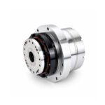 Joint Rotary Actuators Series HAMF
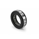 Frameless Torque Motor HBM
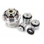 Rotary Actuators
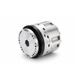 Joint Rotary Actuators Series HAG
 Rotary Actuators Series HPG

Introduction: The Mechanical Fork in the Road
In the lifecycle of machine design, every mechanical engineer eventually reaches a fundamental crossroad when configuring a rotational axis: should the output be a solid shaft or a hollow shaft?
While this choice might initially seem like a minor detail concerning only the physical shape of the output interface, it ripples through the entire engineering project. It dictates how sensors are wired, how much space the machine consumes, how clean the assembly looks, and how well the drivetrain resists twisting under heavy loads. Choosing incorrectly can lead to redesign loops, cable fatigue, and costly assembly delays. This comprehensive selection guide explores the physical trade-offs between a solid shaft actuator and a hollow shaft actuator, giving you a clear framework for optimizing your next machine design.
Solid Shaft Actuators: The Benchmark of Pure Rigidity
For decades, the solid metal shaft was the undisputed standard of power transmission. It is a time-tested architecture built on simplicity and raw strength.
Uninterrupted Metal Core for Maximum Torsional Stiffness
The primary advantage of a solid shaft is its physical continuity. Because there is no central hole or internal boring, the cross-sectional area of the transmission core remains completely uninterrupted. Under heavy rotational loads or sudden acceleration profiles, this solid geometry provides maximum torsional stiffness, meaning the output flange resists twisting or angular deflection better than any hollow equivalent of identical outer dimensions.
Ideal Scenarios for Traditional Direct Power Transmission
Solid shaft actuators are the natural choice for applications where the actuator couples directly to an external gearbox, a heavy-duty timing pulley, or a solid indexing dial where no internal pass-through utilities are required. If your application demands uncompromised structural rigidity and your cables can safely route around the exterior of the mechanism, a solid shaft remains an exceptionally reliable and cost-effective choice.
Hollow Shaft Actuators: The Architectural Game-Changer
As automation evolved toward compact, highly integrated, and flexible architectures, the limitations of routing cables around the outside of a spinning joint became glaringly obvious. Enter the hollow shaft design.
Centralized Routing: Passing Cables and Air Lines Through the Axis
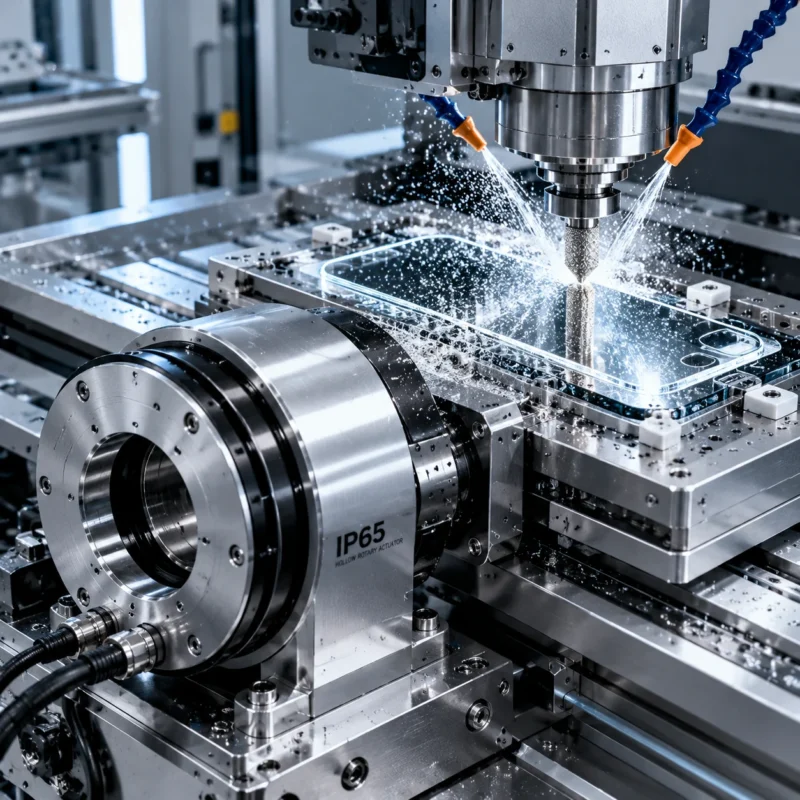
The defining feature of a hollow shaft actuator is its open, axial bore. Instead of forcing sensor wires, motor power lines, vacuum hoses, and pneumatic air tubes to snake around the exterior housing where they risk pinching or fatigue, the hollow center provides a protected internal conduit. Utilities pass straight through the heart of the rotation axis.
Minimizing Footprint in Complex Multi-Axis Gantry Systems
In multi-axis systems like pick-and-place gantries or robotic wrists, space is extremely scarce. By eliminating external cable loops and drag chains, hollow shaft configurations dramatically reduce the physical sweep profile of the moving assembly. This allows machines to pack tighter axes closer together, minimizing the overall machine footprint.
Head-to-Head Comparison: Weighing the Trade-offs
When diving into actuator selection, you must weigh three critical engineering pillars against your specific application demands.
Rigidity and Load Capacity: Solid vs. Hollow
Purely from a physics standpoint, a solid shaft of a given outer diameter will always have higher torsional stiffness than a hollow shaft of the same diameter and material. However, modern engineering compensates for this by utilizing larger-diameter thin-walled hollow structures and high-modulus alloys, allowing high-performance hollow actuators to achieve astonishingly high rigidity while retaining their interior utility channel.
Cable Management and Freedom of Rotation
If your design requires continuous 360-degree rotation or multi-revolution winding, solid shafts force you to rely on expensive slip rings or accept limited-range oscillation to prevent cord-wrapping. Hollow shafts eliminate this restriction entirely, offering unlimited rotation freedom without stressing or twisting internal cables beyond their rated flex limits.
Cost, Complexity, and Maintenance
Solid shafts generally offer a simpler manufacturing process, translating to a lower initial component cost. Hollow shafts require precise internal bearing arrangements and careful mechanical boring, but they drastically reduce long-term maintenance costs by preventing the cable snags, abrasion wear, and downtime associated with external wire management.
Decision Tree: Which Actuator Structure Do You Need?
To simplify your engineering review, ask yourself these three critical questions:
When to Stick with a Solid Shaft
- Does your application require zero internal pass-through of fluids or wires?
- Are you driving an external mechanical load via a direct side-coupled belt or a solid flange coupling?
- Is absolute maximum structural rigidity under extreme shock loads your single overriding priority?
- If yes, choose a solid shaft configuration.
When a Hollow Shaft Becomes Mandatory
- Does your rotating stage or end-effector require continuous or multi-revolution rotation?
- Do you need to route vacuum lines, sensor data, or optical fibers through the center of the axis?
- Are you trying to eliminate external cable tracks to shrink the machine’s physical envelope?
- If yes, a hollow shaft configuration is mandatory.
Conclusion: Aligning Structure with Application Goals
In precision motion control, there is no single “superior” mechanical structure—there is only the structure that aligns perfectly with your application goals. While solid shafts provide the benchmark of pure, unbored rigidity, hollow shafts revolutionize machine architecture by solving the eternal challenge of cable management.
By understanding these structural trade-offs during the early phases of actuator selection, you can build machines that are not only mechanically sound and precise, but also clean, compact, and exceptionally reliable.
FAQ Section: Shaft Configuration Q&A
Q1: Does a hollow shaft actuator inherently have lower torsional stiffness than a solid shaft actuator?
Theoretically, removing the center of a shaft reduces its torsional resistance relative to its outer diameter. However, modern high-performance hollow actuators compensate for this by scaling up the outer diameter slightly and utilizing advanced cross-roller bearings and thick-walled structural housings, matching the rigidity needed for demanding industrial applications.
Q2: Can I convert a solid shaft stage into a hollow setup later if my cabling needs change?
Generally, no. The internal architecture of a solid shaft actuator features a continuous metal core, drive shaft, and solid bearing mounts that block the center. Converting a machine from solid to hollow requires a complete mechanical redesign and replacement of the actuator unit. Therefore, evaluating future cabling needs during initial design is crucial.
Q3: How do I determine the minimum required bore size for a hollow rotary stage?
To determine the correct bore size, bundle all the cables, pneumatic tubes, and fluid lines that must pass through the axis. Measure the cross-sectional area of the bundle and ensure it occupies no more than 60% to 70% of the actuator’s inner diameter. This leaves necessary “free space” to prevent binding, friction, and heat buildup during continuous rotation.