 Joint Rotary Actuators Series HAT
 Joint Rotary Actuators series HAS
 Joint Rotary Actuators Series HAMF
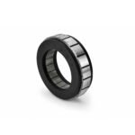 Frameless Torque Motor HBM
 Rotary Actuators
 Joint Rotary Actuators Series HAG
 Rotary Actuators Series HPG

Introduction: Taming the Invisible Electromagnetic Beast
The paradox of modern automation is that as our machines become faster and more precise, they also become more vulnerable to invisible forces. The high-speed switching frequencies required to drive advanced servomotors dynamically create a side effect: high-frequency electromagnetic noise.
If your electrical panel lacks robust noise mitigation, this high-frequency energy will bleed into sensitive control and feedback circuits. The result is a series of frustrating, intermittent “ghost” errors—unexplained encoder faults, erratic axis jumps, or sudden communication timeouts. Preventing these issues requires a disciplined approach to grounding and shielding. This engineering guide outlines the field-proven best practices necessary to protect your servo system from electrical noise and ensure absolute operational stability.
The Physics of EMI: Why Servo Systems Are Prone to Noise
To design an effective defense, you must first understand how electromagnetic interference (EMI) is generated and propagated within automated machinery.
The High dV/dt Transients of Modern Inverter Outputs
Inside a servo amplifier, DC bus voltage is rapidly chopped using high-speed transistors (IGBTs or SiC devices) at frequencies ranging from 8 kHz to over 20 kHz. These sharp switching pulses create extreme voltage change rates over time (high dV/dt transients). Because of these steep voltage slopes, high-frequency electrical currents bypass standard insulation barriers via parasitic capacitance, leaking directly out of the motor power cables and into the machine frame.
Parasitic Capacitance and High-Frequency Coupling
Parasitic capacitance exists anywhere two conductors are separated by an insulator—including between the inner conductors of a motor cable and its outer shield, or between power wires running parallel inside a metal wire duct. High-frequency noise exploits these parasitic pathways, jumping across physical gaps without direct metallic contact to corrupt sensitive low-voltage signals, such as encoder data or analog inputs.
Rule #1 of Cable Shielding: Banish the “Pigtail”
Cable shielding is your primary barrier against radiated and coupled noise, but a shield is only as good as its termination.
The Antenna Effect of Twisted Shield Wires
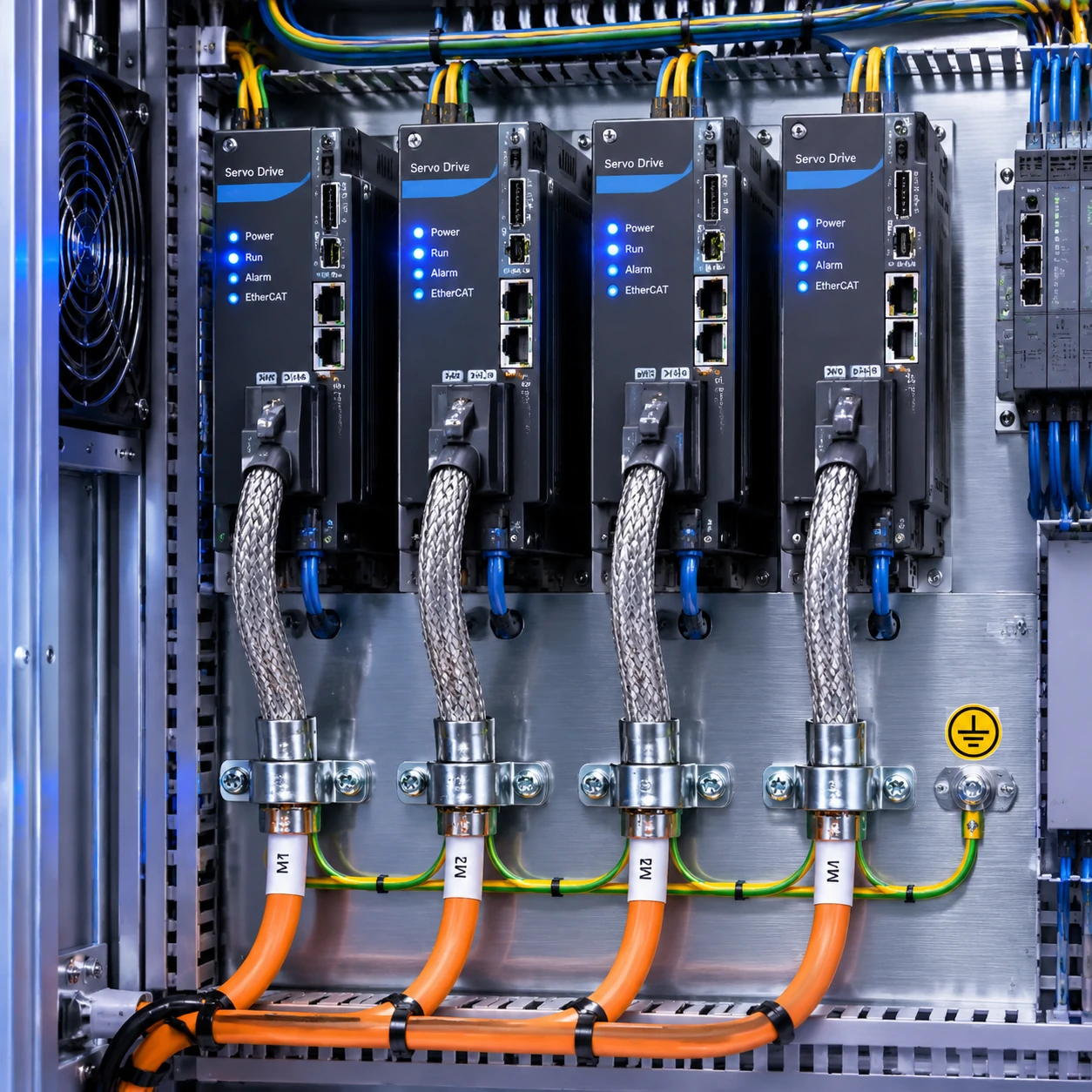
A common mistake made by technicians during control panel assembly is taking the braided copper shield of a motor cable, twisting it into a tight strand (known as a “pigtail”), and screwing it into a standard ground terminal block. At high frequencies, this pigtail acts as an efficient radio antenna, radiating the very noise you are trying to suppress straight into your cabinet.
Implementing 360-Degree Conductive Saddle Clamps
High-frequency noise travels almost exclusively on the outer skin of a conductor (the skin effect). To properly trap this noise, the cable shield must be terminated using a 360-degree connection. Strip the outer cable jacket to expose the braided metallic shield, and clamp it directly to a bare metal backplate using a conductive saddle clamp. This creates a low-impedance path that immediately shunts high-frequency noise currents away from sensitive electronics.
Establishing a Clean Reference: Grounding Topologies
A shield is useless if it dumps noise into a “ground” that is actually floating or shared with noisy high-power loads.
The Power of the Equipotential Ground Plane
The gold standard for industrial control panels is a massive, unpainted, zinc-plated or bare aluminum backplate that serves as an equipotential ground plane. Because high-frequency currents prefer low-impedance paths over long distances, mounting all drive backplates, filter modules, and grounding bars directly onto this solid metallic sheet ensures a uniform zero-voltage reference across the entire enclosure.
Avoiding Dangerous Ground Loops Between Drives and Controllers
If components are grounded at multiple, disparate points with varying electrical potentials, circulating currents called ground loops will form, injecting massive electrical noise directly into signal references. Implement a strict star-grounding topology, running dedicated, heavy-gauge copper conductors from each major subsystem directly back to a single master earth stud.
Practical Routing Guidelines for Power and Signal Separation
Distance and geometry are powerful passive defenses against electromagnetic coupling.
Physical Distance Rules for Motor Power vs. Encoder Feedback
Never bundle high-voltage motor power cables and low-voltage encoder feedback cables together inside the same wire raceway. Maintain a physical separation of at least 150mm to 300mm between power conduits and signal lines. If space constraints force them to share a metal wire duct, install a grounded metallic divider plate between them to act as a physical Faraday barrier.
Crossing Paths at Right Angles to Minimize Cross-Coupling
When power and signal cables must intersect inside your machine layout, always route them to cross each other at a 90-degree right angle. Parallel runs maximize electromagnetic coupling, whereas perpendicular intersections minimize the mutual inductance area, drastically reducing cross-talk between circuits.
Conclusion: Hardwiring Reliability Into Your Machine
Mastering grounding and shielding is not an artistic exercise or an afterthought to be addressed only when a machine fails certification testing. It is a fundamental engineering discipline that dictates whether a high-performance machine will run smoothly for a decade or plague maintenance teams with random diagnostic faults.
By eliminating pigtail terminations, enforcing 360-degree shield bonding, utilizing an equipotential backplate, and maintaining disciplined cable segregation, you build a robust electrical fortress. Prioritizing these EMC best practices ensures that your servo system remains immune to electrical noise, delivering the uncompromised precision and system reliability expected of modern automated machinery.
FAQ Section: Servo Grounding Engineering Q&A
Q1: Should motor cable shields be grounded at both ends or only at the servo drive?
For high-frequency electromagnetic interference (EMI), motor cable shields must be grounded at both ends (360-degree clamped to the drive backplate at the cabinet end, and 360-degree clamped to the motor housing or connector shell at the motor end). Grounding only at one end turns the ungrounded end into an antenna, rendering high-frequency shielding virtually useless.
Q2: How does an improper ground cause encoder communication faults?
If high-frequency noise currents from the PWM inverter cannot find a low-impedance path back to the drive via a proper 360-degree shield, they will seek alternative paths—such as the signal shield of the encoder cable or the internal ground reference of the controller. This stray current induces voltage spikes in the encoder data channels, corrupting digital packets and triggering immediate communication error faults.
Q3: What is the maximum acceptable impedance for an industrial machine ground network?
While safety codes (like NEC or IEC) focus primarily on low-frequency fault-clearing safety (often requiring under 1 to 0.1 ohms), high-frequency EMC requires minimizing inductive impedance. This is why surface area (using wide metal plates and 360-degree clamps) matters far more than wire gauge alone when dealing with the high dV/dt switching frequencies of modern servo systems.