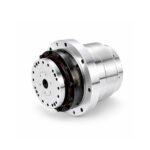
 Joint Rotary Actuators Series HAT
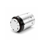 Joint Rotary Actuators series HAS
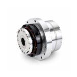 Joint Rotary Actuators Series HAMF
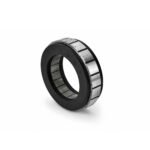 Frameless Torque Motor HBM
 Rotary Actuators
 Joint Rotary Actuators Series HAG
 Rotary Actuators Series HPG

Introduction: The Hidden Bottleneck of Cycle Time
In the relentless rush for speed in industrial automation, engineers obsess over top speed and maximum acceleration. Machines are engineered to tear across a workspace in fractions of a second. Yet, a startling amount of production time is wasted not while the machine is moving, but when it is trying to stop.
This delay is known as settling time—the duration between the moment a moving axis reaches its target destination and the exact moment it comes to absolute rest, free of residual vibration. If your machine overshoots its target or shakes before stabilizing, your controller must wait for the system to calm down before executing the next command. This “cost of waiting” kills overall machine throughput. This guide explores the mechanical and software strategies required to minimize settling time in point-to-point motion.
What is Settling Time and Why Does It Matter?
To optimize performance, you must first understand the distinction between reaching a coordinate and being ready to work.
Reaching the Target vs. True System Stability
When a motion controller commands a motor to move to a specific position, the encoder reports when the physical axis crosses that coordinate. However, due to momentum and mechanical elasticity, the load often flies past the mark (overshoot) or bounces back and forth like a spring. The true settling time only ends when the oscillations decay within a defined error band (e.g., within
±1±1encoder count).
The Cost of Waiting: How Sluggish Stopping Kills Productivity
In high-frequency applications like component insertion, laser cutting, or liquid dispensing, settling time can account for 30% to 50% of an entire operational cycle. If you can slash your settling time from 50 milliseconds to 10 milliseconds, you instantly unlock a massive boost in machine throughput without ever increasing your top motor speed.
The Root Causes of Extended Settling Times
Why do systems shake and linger after a move? The culprits are usually a combination of control dynamics and mechanical physics.
Mechanical Compliance and Resonance Traps
Every machine has a natural resonant frequency. If your drivetrain features flexible couplings, long timing belts, or thin-walled brackets, the mechanical structure will act like a spring. When the motor executes a sudden stop, the inertia of the payload causes the structure to ring. This mechanical compliance is the primary reason systems suffer from prolonged settling delays.
Aggressive Tuning Causing Unwanted Overshoot
In an attempt to make a machine snap to its target instantly, engineers often crank up the Proportional (P) gains in their servo loops. While this creates a very aggressive initial response, it frequently causes severe overshoot. The drive must then aggressively reverse direction, creating a secondary bounce that severely lengthens the overall settling phase.
Strategy 1: Optimizing the Motion Profile
The first line of defense against settling delays happens in the trajectory planner before the motor even starts moving.
Softening Transitions with S-Curve Trajectories
Traditional trapezoidal profiles feature abrupt changes in acceleration, introducing infinite jerk that shocks the mechanical frame. Transitioning to an S-curve motion profile rounds off these sharp acceleration corners. By easing the transition into and out of movement, you prevent the machine frame from acting like a tuning fork.
Utilizing Advanced Jerk Limits to Prevent Ringing
Configuring strict jerk limits ensures that high-frequency vibrational energy is never injected into the mechanical system during acceleration or deceleration. Because the machine starts its stop smoothly, it arrives at the destination with minimal residual kinetic energy, virtually eliminating post-move ringing.
Strategy 2: Advanced Servo Tuning and Filtering
Once the trajectory is optimized, the control loop must be fine-tuned to handle the physical reality of the machine.
Fine-Tuning the Velocity and Position Loops
Achieving clean settling requires a balanced cascade control loop. Your velocity loop must be tuned for high bandwidth so it can aggressively counteract disturbances, while your position loop must be optimized to prevent tracking lag without introducing step-response overshoot.
Deploying Notch Filters to Erase High-Frequency Vibrations
If a specific mechanical resonance continues to plague your system, software adjustments alone will not suffice. Modern drives allow you to deploy “Notch Filters.” These specialized digital filters target and attenuate the exact resonant frequency of your machine frame, allowing you to run high control gains safely and eliminate high-frequency chatter entirely.
Strategy 3: Hardware Upgrades for Ultimate Mechanical Rigidity
No amount of software magic can completely compensate for a fundamentally “spongy” mechanical structure.
Why High Torsional Stiffness is the Ultimate Cure for Jitter
If your goal is instantaneous stability, structural rigidity is your best friend. High torsional stiffness ensures that when the motor stops, the load stops with it, preventing structural wind-up and internal deflection.
Choosing Zero-Backlash Actuators for Instantaneous Stops
This is why upgrading to precision hardware is so transformative. Utilizing zero-backlash actuators—such as strain wave gear integrated units or direct-drive frameless motors—creates an unyielding connection between the power source and the load. There are no gear teeth to clatter and no belts to stretch, enabling the system to stop on a dime.
Conclusion: Speed is Nothing Without Stability
True machine speed is not just about how fast an axis can travel across an empty space; it is about how cleanly, decisively, and accurately it can complete a task upon arrival.
By combining intelligent motion profiling, precise servo tuning, and uncompromising mechanical rigidity, engineers can systematically eradicate settling delays. When your automation systems master point-to-point motion without the cost of waiting, your productivity will reach unprecedented heights.
FAQ Section: Settling Time Engineering Q&A
Q1: How is settling time measured in a modern motion controller?
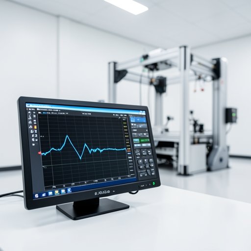
Settling time is measured using the motion controller or drive’s diagnostic software scope. It is calculated from the exact moment the position command reaches its final destination to the moment the actual encoder feedback position permanently enters and stays within a predetermined narrow error band (e.g.,
±2±2encoder counts).
Q2: Can I use software damping to fix a mechanically “spongy” robot arm?
Software features like derivative gain, low-pass filters, and friction compensation can help mask or dampen structural flexibility. However, they cannot fully cure a mechanically weak design. If a structure lacks fundamental rigidity, physical upgrades (such as stiffer brackets or zero-backlash actuators) will always yield superior results.
Q3: What is the relationship between closed-loop bandwidth and settling time?
Generally, a higher closed-loop bandwidth allows the servo drive to correct errors faster, which can shorten settling time. However, if the bandwidth is pushed higher than the mechanical resonant frequency of the machine, it will excite vibrations, causing instability and actually increasing the settling time. Bandwidth must always be balanced with mechanical stiffness.